Summary of Twitter garage door using the GE Choice ALERT system & Arduino
This project modifies a GE Choice-Alert wireless garage door monitor to notify via Twitter using an Arduino with Ethernet shield. It involves opening the monitor, soldering wires to the zone 1 LED contacts, routing wires through the battery cover into a project box, mounting a screw terminal, and connecting to the Arduino analog input and ground. The Arduino posts a startup tweet and alerts when the door is open.
Parts used in the Garage Door Twitter Notifier:
- Project enclosure for Arduino + Ethernet shield
- Arduino (Diecimila used)
- Arduino Ethernet shield
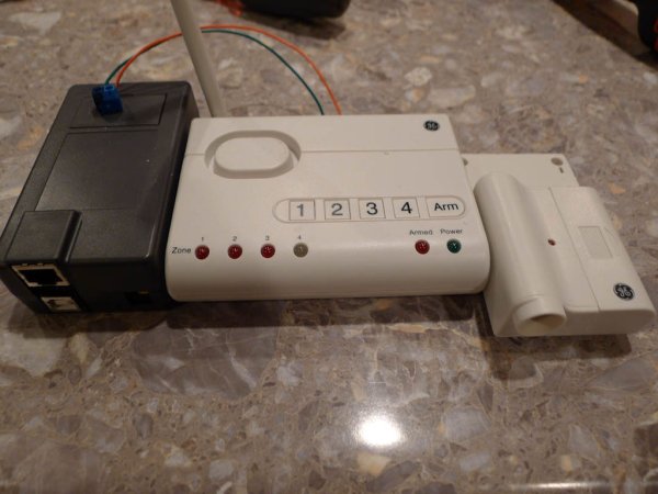
- GE Choice Alert wireless-control center
- GE Choice-Alert wireless garage door sensor
- Screw terminal
- Wires for soldering
- Dremel (for routing plastic)
- Drill (for holes in battery cover and project box)
You know that feeling of driving away from your house almost getting to work and saying “Now Did close the garage door?” . I hate that feeling and seeked out to resolve it in the smiplest/cheapest way I could. The starting point was of course Arduino. This project ended up being simpler than I could of imagined but it was not my best effort (as it was my first real project making something useful with the Arduino).
Step 0: Sync the garage door monitor to the base station. Unplug everything then.
Step 1:
The first thing to do is unscrew the two screws in the back and the one under the battery cover. Then you can pry the back off (Be careful as getting the battery contacts out is reallyyyy sorta a pain.
Step 2:
Flip over and find the LED for zone 1 (labeled 1!). Then turn it back to the PCB side and find the contacts. I soldered one wire for where I found the ground was (Green) and another red wire for the -. I found which was which by trial and error using my arduino.
NOTE: Soldering there’s wires are hard, i dunno if it was my crappy soldering iron or what but it was hard to heat up the metal already on the PCB and get my wires soldered to it on a solid way. If you are enterprising enough you can solder two wires to each of the zone alarms and have this tweet you when say someone is detected by their wireless motion sensor, or the door sensor goes off etc…
Step 3. I used a dremel to edge out some of the plastic on the battery cover so the wires could come out from the PCB into the battery area. This is where I also attached a (superficial perhaps) board to connect more wires to that ultimately lead to the screw terminals attached to the arduino. The idea of the board was make sure there was slack in the system so the wires don’t get yanked out of the delicate soldering on the LED pins on the PCB of the alarm base station.
Step 4: Drilling out the battery cover. This is simple drill I used and made the holes so the wires could pop out of it…
Step 5: Mark where the screw terminal should go in the project box and drill the holes, then on the other side solder in the screw terminal with the wires that will goto the arduino/ethernet controller.
Step 6: Finally put in the arduino and ethernet controller shield into the project box and connect the wires to ground respectively and analog 0. Then close the box up.
#if defined(ARDUINO) && ARDUINO > 18 // Arduino 0019 or later
#include
#endif
#include
//#include Only needed in Arduino 0022 or earlier
#include

byte mac[] = { 0xDE, 0xAD, 0xBE, 0xEF, 0xFE, 0xED };
byte ip[] = { 192, 168, 0, 23 };
Twitter twitter("read on how to set this");
char msg[] = "Garage Door is OPEN";
char msgStartup[] = "Garage door monitor is online!";
boolean failed=false;
boolean blinkTime=false;

boolean doorOpen=false;
int alertcounter=0;
int resetcounter=0;
int diodePin=0;
int val;

int randomValue;
void setup()
{
delay(1000);
Ethernet.begin(mac, ip);
Serial.begin(9600);
pinMode(13, OUTPUT);
Serial.println("connecting ...");

sendStartupTweet();

}

void sendStartupTweet()
{
if (twitter.post(msgStartup)) {
int status = twitter.wait();
if (status == 200) {
Serial.println("OK.");

} else {
Serial.print("failed : code ");
Serial.println(status);
failed=true;
}
} else {
Serial.println("connection failed. Startup");
failed=true;
}
1. Project Enclosure for the Arduino + Ethernet shield from amazon.
2. Arduino, in my case the old Diecimila. You all know and love the arduino, found online about 23$
3. Arduino Ethernet shield ~ 40$
4. GE Choice Alert wireless-control center
5. GE Choice-Alert wireless garage door sensor
6. Screw Terminal
For more detail: Twitter garage door using the GE Choice ALERT system & Arduino
- How do you access the LED contacts on the GE Choice-Alert base station?
Unscrew two screws in the back and one under the battery cover, pry the back off, flip to the PCB side and locate the zone 1 LED contacts. - Can the monitor be connected to an Arduino?
Yes; the project solders wires from the zone 1 LED contacts to the Arduino ground and analog 0. - What modifications are made to route wires out of the battery cover?
A Dremel is used to edge out plastic for wire passage and holes are drilled in the battery cover for wires to pop out. - How are wires protected from being yanked at the LED solder points?
A small board is attached inside the battery area to provide slack and secure connections before reaching the screw terminal. - Where are the screw terminals mounted?
Mark and drill holes in the project box, then solder the screw terminal on the other side with wires going to the Arduino/Ethernet controller. - Which Arduino pins are used for the connection?
The wires connect to ground and analog 0 on the Arduino. - Does the Arduino send a startup notification?
Yes; the sketch posts a startup tweet using the Twitter library with the message Garage door monitor is online!. - What message is sent when the door is detected open?
The sketch sends the message Garage Door is OPEN when the door is detected open.