Summary of Analog VU meter and Clock using Arduino
This project recreates an analog VU meter that doubles as a clock. An Arduino reads audio from a 3.5mm input and drives two 5V analog panel meters via PWM to show sound levels; when no audio is detected it switches to clock mode using a DS1307 RTC. Optional LED backlighting was added inside the meters. Assembly uses a protoboard, potentiometer for sensitivity, tactile buttons for time setting, resistors for audio isolation, and standard USB power.
Parts used in the Analog VU Meter and Clock:
- 2, 5V analog panel meters
- Arduino (Pro Mini used)
- DS1307 real time clock module
- Protoboard
- 10K potentiometer
- 2 tactile switches (buttons)
- 4 10K resistors
- 4 white LEDs (optional)
- USB cable (for 5V power)
- 3.5mm audio cable
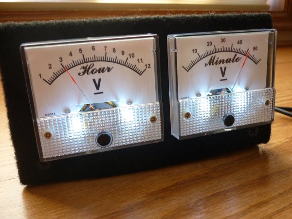
This project brings back the old time Analog VU Meter, with the added functionality of a neat looking clock! When you turn off your music the meters automatically swing into to clock mode. Behind it all is the popular and easy to use Arduino.
This is my submission for the Make-to-Learn Youth Contest:
What did you make?
I made an old style analog VU meter and Clock using 2 analog panel meters, an Arduino, a real time clock, and other simple components. How it works: The unit plugs into a standard 3.5mm speaker jack. The Arduino reads the sound levels and converts it into electric pulses (PWM) to control the analog meters. When no sound is detected, the unit automatically changes to Clock mode and displays the time which is read from the real time clock circuit.
How did you make it?
I got the idea to make an analog VU meter from seeing them used in older audio receivers and amplifiers. I was always intrigued by the effect of a needle “dancing” to the beat of music. With my basic knowledge of electronics and the Arduino platform, I decided that I could make one myself. After searching around the internet to see if anyone had done anything similar, I found that many people create Clocks with analog panel meters. Well, why not include both functions?
Where did you make it?
I made this at home by myself. I like to listen to music a lot and I am always tinkering and playing with electronics. I thought that this would be a fun project to compliment my speaker system which I also built myself.
What did you learn?
I learned a lot from this project. The hardest thing to get right was the programming. I have never worked with analog panel meters before, so getting them to display time and sound accurately was challenging. For example: It was hard to get both meters to point exactly straight up at 6:30. I also learned that connecting the Arduino directly to an audio source can distort the audio. To fix this, I added some resistors and the distortion went away.
Step 2: Meter lights
This step is completely optional, but I decided to put some lighting inside my meters.
First, I took the covers off the meters and drilled two small holes for the LEDs. Then I simply hot glued the LEDs into place. Be careful when drilling and hot gluing because the inside of the meters are relatively fragile.
It is better to use diffused LEDs for this application, but I did not have any diffused white LEDs around. So, I diffused some clear LEDs by using some sandpaper.
Don’t forget resistors!
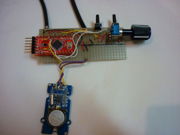
Step 3: Assembly
The assembly is pretty straight forward. See the pictures for more details.
Note: If you only want to use it as a clock, you do not need the audio cable or the potentiometer.
Wiring goes as follows:
– USB red wire (5v) to VCC
– USB black wire to GND
– 3.5mm Audio left channel to 10K resistor to Analog 1
– 3.5mm Audio right channel to 10K resistor to Analog 2
– 3.5mm Audio ground to GND
– Potentiometer to Analog 0 (follow potentiometer wiring)
– Buttons – Left/Down to Digital 2 (follow button wiring)
– Right/Up to Digital 3
– DS1307 RTC – SDA to Analog 4
– SCL to Analog 5
– Left Analog Meter to Digital 5 (PWM)
– Right Analog Meter to Digital 6 (PWM)
Materials
Shopping List:
– 2, 5v Analog panel meters (Amazon) or (Amazon)
– Arduino (I used the pro mini) (Amazon)
– DS1307 Real time clock (Amazon)
– Protoboard (Amazon)
– 10K potentiometer (DigiKey)
– 2 tactile switches (DigiKey)
– 4 10K resistors (DigiKey)
– 4 white LEDs (optional) (DigiKey)
– USB cable (DigiKey)
– 3.5mm cable (DigiKey)
Total cost is around $47. It will be less if you have some of these parts already.
For more detail: Analog VU meter and Clock using Arduino
- How does the unit detect audio and drive the meters?
The Arduino reads audio levels from the 3.5mm input and converts them into PWM pulses to control the analog meters. - Can the meters display the time when no music is playing?
Yes. When no sound is detected the unit automatically switches to Clock mode using the DS1307 RTC. - What power source is used for the project?
The unit is powered by a USB 5V connection (USB red to VCC, USB black to GND). - Do I need the audio cable if I only want clock functionality?
No. If only using it as a clock you do not need the audio cable or the potentiometer. - How are the audio channels connected to the Arduino?
3.5mm left and right channels go through 10K resistors to Analog 1 and Analog 2 respectively; audio ground connects to GND. - Where are the meters connected on the Arduino?
The left analog meter is connected to Digital 5 (PWM) and the right analog meter to Digital 6 (PWM). - What is the role of the potentiometer and buttons?
The potentiometer connects to Analog 0 for adjustment (e.g., sensitivity); buttons connect to Digital 2 and Digital 3 for control like setting time. - How were the meter lights implemented?
Meter covers were removed, small holes drilled for LEDs, LEDs hot glued inside, and sandpaper used to diffuse clear LEDs; resistors were used with the LEDs. - How was audio distortion avoided when connecting to the Arduino?
Adding resistors between the audio source and Arduino removed the audio distortion.