Summary of Smart Phone Controlled Arduino Mood Light with Alarm
Smart Phone Controlled Arduino Mood Light with Alarm summary: A NeoPixel-based mood lamp using an Arduino, DS3231 RTC, HC-05 Bluetooth, and LDR to change colors by time-of-day, allow smartphone control, auto-disable in bright rooms, and support wake/sleep alarms with chromotherapy-based color choices.
Parts used in the Smart Phone Controlled Arduino Mood Light with Alarm:
- Neo Pixel LED strip
- Arduino (e.g., Pro Mini)
- DS3231 RTC module
- HC-05 Bluetooth module
- LDR (light dependent resistor)
- 100K resistor
- 12V power supply / adapter
- Wires and connectors
- 3D printed or other enclosure
Smart Phone Controlled Arduino Mood Light with Alarm
I recently purchased the Neo Pixel LED strip and was quite impressed by the way it works. The tiny LED’s have an inbuilt driver IC which helps us to control each LED individually and can produce a wide spectrum of colors. Being a garish person who is obsessed with colours I really loved watching these tiny LED’s changing colors so I decided to build something on my own and leave it coloring my bedroom during night times.
I not only wanted these LED’s to change colors but should also have logic reasoning behind it. That is when I came across the article by Mr. Stephen Westland who is a professor of Color Science and Technology at University of Leeds. He claims that when humans are exposed to coloured lights they respond, both physiologically and psychologically based on the color. This concept is not new and has been widely practised in the name of Chromotherapy and the device used to do this is called a Mood Lamp.
So I finally settled to dig deep into chromotherapy and build a Mood Lamp which could change colors based on the time of the day and can also be controlled form the mobile phone. Apart from that I also added a LDR to turn it off automatically during day time and also an option to set a wake up alarm which will wake you up with a bright orange colour (sunshine) and another alarm that puts the LED’s in sleep mode with mild purple (night sky) color to doze you into sleep. Sounds interesting right? So let’s get building.
Chromotherapy – Mood Lamp
But there are lots of so called DIY mood lamps out there which just randomly change colour without any purpose behind it. After a bit of searching I found that a mood lamp should have a minimum of certain lumens brightness and should also change colours gradually with varying intensity. Each colour has a different impact on both mental and physical level. I have tabulated the impact against each colour in the below table.
|
Colour |
Physiological impact |
Physical impact |
|
Red |
Gives more Energy, Boosts Sexual Desires |
Kidney, Backbone, sense of smell |
|
Yellow |
Improves Digestion, Kills Depression |
Stomach, Liver, Intestine |
|
Blue |
Lowers Blood Pressure, Calm Down People |
Migraine headache, throat, ears and mouth |
|
Green |
Stimulates Growth and strengthens muscle |
Bones, tissues, immune system |
|
Purple |
Sleep Inducer Emotional and Mental Balance Decreases Sexual desires |
Nervous system, eyes |
|
Orange |
Stimulates creativity |
Breathing, Brest feeding |
|
Pink |
Purifies Blood |
Blood, arteries, veins |
So based on this data I have designed the mood Lamp to change its colours based on what time of the day it is. Of course I have added some personal flavour, so feel free to edit the program accordingly.
Materials Required
Enough science we are supposed to be working with electronics, so let’s gather the required components.
- Neo Pixel LEDs
- Arduino
- DS3231 RTC module
- HC-05 Bluetooth Module
- LDR
- 100K resistor
- 12V Power supply.
Circuit Diagram
The complete circuit diagram for this Bluetooth Controlled Arduino Mood Lamp Project is given below.
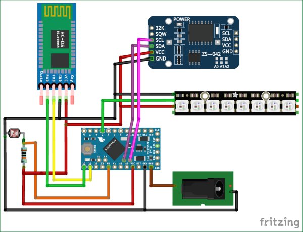
As you can see, we have used modules and hence the connections are pretty simply. For keeping track of the current time we have used the DS3231 Real Time Clock (RTC) module. This module works with the help of I2C communication and can be powered directly with 5V pin of the Arduino. The SDA and SCL pins are connected to the I2C pins A4 and A5 respectively.
Next we have used the HC-05 Bluetooth module. Through this Bluetooth connection we can set the required colour on the LED and also set a sleep time and wake up time for the LED. The Bluetooth module is powered with the 5V pin as well and the Tx and Rx pins are connected to Arduino through pins 11 and 10 respectively.
It is pointless to glow the LEDs when the room is very bright, hence we have used an LDR to detect brightness in the room and if it is very bright the LEDs turn off automatically and turns back on only when the room is dark is enough. We have formed a potential divider network with one resistor being the LDR itself and the other a 100K resistor and connect it to pin A0 of Arduino, this way a the resistance of LDR varies based on light the voltage read by the Arduino will also vary. Learn more about interfacing LDR with Arduino here.
Finally the neo pixel is connected to pin 6 of Arduino which is a PWM pin and is again powered by the 5V pin (vcc) of the Arduino. I have used an Arduino Pro-mini for my project since it is smaller and would be handy while packing it inside an enclosure. You can use any board of your choice. The complete set-up is powered by a 12V adapter which is connected to the RAW pin of the Arduino. The on board voltage regulator on Arduino converts this 12V to 5V which is then used to supply 5V to power all the modules through the vcc pin.
Neo Pixel LEDs and How They Work
The primary and cool component of this project is the neo Pixel LED. The idea for the Neo pixel LEDs were originally by the Adafruit industries in which they use an LED driver IC WS2812 inside an RBG LED. This driver IC can receive a control signal from a controller like Arduino and based on the control signal it can control the intensity of the RBG color thus helping us to achieve the required color.
You can connect as many as of these LED in series and the cool feature is that each of these LED can be addressed individually meaning each LED can be made to glow in different colors by tweaking the control signal accordingly. So remember that unlike an normal LED you can power a neo pixel using just a power supply, it has three pin namely the Vcc, ground and data. The Vcc and ground pin is used to power the Led which can range from 3.3V to 5V and the data pin is used to send the control signal which decide that which Led should glow in which color.
Using the Neo pixel LED is pretty simple because of the library provided by Adafruit itself. Today there are many different types of Neo Pixel led available in the market from different vendors and they use different driver IC. But all of them can be controlled by this Adafruit library. We have previously interfaced NeoPixel with Arduino.
Programming Arduino for Mood Light
The complete program for this Neo-pixel mood light with Arduino project is given at the end of this page, which can be used as such after you have added the required libraries. In this section I will discuss few important snippets from the code which could help you modify the project as required. The program is quite big around 300 lines so if you feel grumpy trying to understand anything feels free to post your questions on the forums and as always complete Arduino program can be found at the end of this article.
As always we begin the program by adding the required libraries for the project in this case the following libraries are needed.
#include <SoftwareSerial.h> //Bluetooth module works with software serial
#include <Adafruit_NeoPixel.h> //Library for Neo Pixel (Download from Link in article)
#include <DS3231.h> //Library for RTC module (Download from Link in article)
#include <EEPROM.h> //Library for EEPROM (Pre-Loaded into Arduino)
The Bluetooth module works though serial communication; I do not prefer using the hardware serial pin (0 and 1) for that since I will be using the serial monitor to debug the program, so we include the software serial library into our program. This library will be present in your IDE by default.
Next we use the Adafruit Neo Pixel library from Adafruit that we discussed in previous heading. You can download the Adafruit Neo pixel library using the link, which will download the ZIP file from the GitHub. Then you can use the sketch -> Include Library -> Add .ZIP library option to add this ZIP file into your Arduino IDE.
Similarly you can also download the DS3231 library for the RTC module and add it the same way. Finally we have EEPROM library which are already pre-loaded into the Arduino library. We just have to add the library to store the wake up alarm and sleep alarm time in EEPROM so that when the Arduino re-boots after a power failure it remembers when to go to sleep and when to wake up.
The Neo Pixel LEDs can produce a wide range of colours, but we are not interested in all the colours for our mood light except for 8 of them which are Red, Orange, Yellow, Green, Cyan, Blue, Purple and Pink. To get each of these colours we have to pass the respective value of it. So we define the value of each colour using the macros as shown below.
#define Red 1
#define Orange 20
#define Yellow 30
#define Green 70
#define Cyan 100
#define Blue 130
#define Purple 200
#define Pink 240
Next we have to declare to which pins we have connected the neo Pixel and how many LEDs are present on the Neo Pixel strip. In my case I have connected the Neo pixel to pin 6 as shown in the circuit diagram above and I have a total of 5 LEDs on my strip so my code looks like
Adafruit_NeoPixel strip = Adafruit_NeoPixel(5, 6, NEO_GRB + NEO_KHZ800); //5 LEDs on PIN-6
There are a lot of global variables declared in the program in the next line, what you might be interested to play around is with the array declarations. There are two arrays namely the morning_rainbow and evening_rainbow each consisting of 4 colours. I have selected Red, Orange, Green and Pink to be the morning colours and Yellow, Cyan, Blue and Purple to be the evening colours based on the chromo therapy table that we discussed above you can change it as you wish
//array declarations
char current_rainbow[8] = {}; //the main array
char morning_rainbow[4] = {Red, Orange, Green, Pink}; //colours to show during day time
char evening_rainbow[4] = {Yellow, Cyan, Blue, Purple}; //colours to show during night time
char all_rainbow[8] = {Red, Orange, Yellow, Green, Cyan, Blue, Purple, Pink}; //colours that can be controlled thorugh Bluetooth
Inside the void setup function we initialise the Bluetooth module and Serial monitor at 9600 baud rate. The Bluetooth is used to communicate with our phone and the serial monitor is used for debugging. Simply launch the serial monitor and you can monitor all the vital variables in the program. Apart from that we also read the EEPROM values if the user has set them previously and store them in the respective variables
void setup(){//Execute once during the launch of program
Initialize_RTC();
Bluetooth.begin(9600);
Serial.begin (9600); //for debugging
strip.begin();
strip.show(); // Initialize all pixels to ‘off’
Bluetooth.println(“Mood Lamp Alarm -CircuitDigest”);
Serial.println(“Mood Lamp Alarm -CircuitDigest”);
//If anything was stored previously in EEPROM copy it to the alarm variables
sleep_alarm_hour = EEPROM.read(0);
sleep_alarm_minute = EEPROM.read(1);
wake_alarm_hour = EEPROM.read(2);
wake_alarm_minute = EEPROM.read(3);
}
Inside the main loop, we begin the program by reading the value from the LDR, if the room is very bright the program dims all the LEDs thus turning it off and then waits for the room to get bright again. The function Interactive_BT is also checked when the room is bright so that the user can still force the lights to turn on from the mobile phone. Here I have select 800 as the threshold value but if you want to lamp to work even in bright day light you can simply increase the value of 800. Then range is form 0-1024.
while (lightvalue>800) //IF the room is very brigt (you can increase this values to make it glow even duringf day)
{
for (int i=0; i<=5; i++) //turn of all LED
{
strip.setBrightness(0); //by setting brightness to zero
strip.show();
}
lightvalue = analogRead(A0); //kepp checking if the room is getting darker
Serial.print(“Too bright to glow: “);
Serial.println(lightvalue); //for debugging
Interactive_BT(); //Also check if the user is trying to access through bluetooth
delay(100);
}
The interactive_BT is the function inside which the user can set the alarm or control the Lamp from his phone. The code inside this function is self explanatory through comment section, so I am not going line by line. The speciality of the program is that it can use any Bluetooth application from android app store or Iphone store and still can interact with it.
Next we read the current time and update the time object “t”. From that we split the hour and minute value using the t.hour and t.min and store it in the variable current_time_hour and current_time_minute respectively.
t = rtc.getTime(); //get the current time
current_time_hour = t.hour; //get hour value
current_time_minute = t.min; //get minute value
In this program I am changing the color of the Neo pixel for every 5 seconds, so the next segment for code will be execute only once in every 5 seconds. Inside this segment we increase the value of count and call the function called glow_rainbow. This function glows the led based on the colors stored in the current_rainbow array. So before calling this glow rainbow we have to load current rainbow using a set of colors from either morning_rainbow or evening_rainbow based on the time of the day as shown below.
if (sleeping == false) //If we are not sleeping
glow_rainbow(colour_count); //dsplay the colours
if (sleeping == true) //if we are sleeping
night_lamp(); //display the night lamp effect
if (t.hour>=17) //During evening time
{
for (int i=0; i<=3; i++)
{ current_rainbow[i] = evening_rainbow[i]; delay(100);} //copy evening raninbow into current_rainbow
}
else //During Morning
{
for (int i=0; i<=3; i++)
{ current_rainbow[i] = morning_rainbow[i]; delay(100);} //copy mornign rainboe into current rainbow
}
Inside the glow_rainbow function we use two for loops one to dim the LED and other to increase the brightness of the LED based on the required colour. This required colour is selected from the array current_rainboe[count] where count decides the current colour form the array. There are totally 5 LED in my strip so I have used variable i upto 5, the value of j can be fiddled around between 0-255 according to how much ever brightness you want to reduce
void glow_rainbow(int count)
{
for (int j=150; j>=10; j–) //decrease the brightness to create dim effect
{
for (int i=0; i<=5; i++) //do it for all 5 leds
{
strip.setBrightness(j);
strip.show();
}
1 delay(2);
}
for (int j=0; j<=255; j++) //increase the brightness
{
for (int i=0; i<=5; i++) //do it for all 5 leds
{
strip.setPixelColor(i,Wheel(current_rainbow[count]));//select the colour based on count value
strip.setBrightness(j);
strip.show();
}
delay(10);
}
}
The function wheel is directly taken from the Adafruit example program. It takes in a value from 0 to 255 and produces a colour based on the value. This value is what we defined initially in our program using the #define macros. The function is shown below.
// Input a value 0 to 255 to get a color value.
// The colours are a transition r – g – b – back to r.
uint32_t Wheel(byte WheelPos) {
WheelPos = 255 – WheelPos;
if(WheelPos < 85) {
return strip.Color( (255 – WheelPos * 3), 0, (WheelPos * 3) );
}
if(WheelPos < 170) {
WheelPos -= 85;
return strip.Color(0, (WheelPos * 3) , (255 – WheelPos * 3) );
}
WheelPos -= 170;
return strip.Color((WheelPos * 3), (255 – WheelPos) * 3, 0);
}
This line strip.Color(x,y,z) is an important line which decides the colour of the LED. The variables x,y and z each take a value from 0-255 and based on the value it decides the amount of Red, Green and Blue light the LED should emit. So x,y ad z directly controls the Red, Green and Blue light intensity of the LED pixels.
Controlling and Setting Alarm through Smart Phone
Once you have made the connection as per the circuit diagram and have uploaded the code given below you can test the circuit. I would also recommend opening the serial monitor to check how the hardware is responding to the program. Once you are done with that you can open your Bluetooth application on the mobile phone.
I am using the Bluetooth terminal application from Play Store but you can use any Bluetooth application which helps you to read and write data through Bluetooth connection. Make sure you have paired the Bluetooth module with your phone using the password “1234” before launching the application. Once the application is launched connect to your Bluetooth device which should be normal named as “HC-05”.
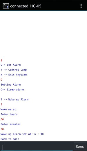
To begin communications just send a random variable from the phone, in this case I have sent ‘g’. This will initiate Interactive Bluetooth communication mode in the program and you will get the following screen.

From here simply follow the on screen instruction to set alarm or for controlling the lamp for your required colour by simply send numbers. For example I have set the morning alarm here.
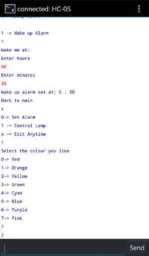
Similarly you can also set the evening alarm and can also control the Lamp by sending the number for required colour as shown below. The complete working can also be understood form the video linked at the end of this project.
3D Printing the Enclosure for Arduino Mood Light
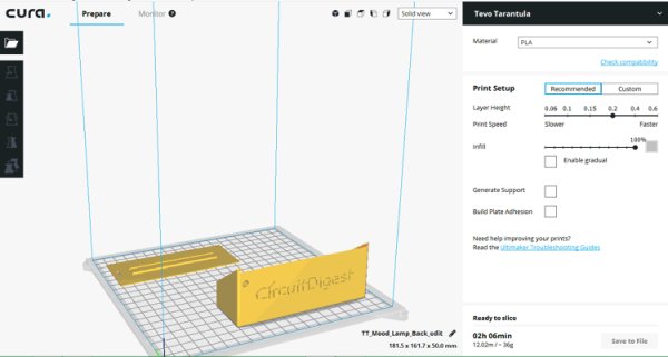
As I said I made this project to be left working in my office or in my living room so it requires a good enclosure for housing all the electronics. Also it hurts our eyes to look at the pixel directly when they glow. So I decide to 3D print my enclosure using my Tevo tarantula printer and hence went on to design my enclosures.
The complete design files are available for download from thingiverse. You can also print your own if you have 3D printer or simply can use wood or acrylic to build an enclosure of our own. My print setting is show in the image below.
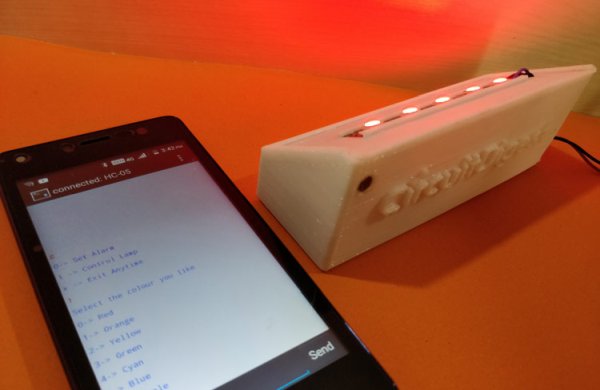
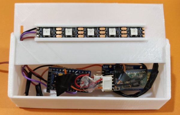
After printing you can push the LDR into the small hole provided and the LED strip can be slide into the top case. After assembling, my hardware looked something like this as shown below.
All that is left to do is power the set-up using a 12V adapter and set the alarm using the Bluetooth option as discussed above and leave in illuminating your room. Hope you liked the project and enjoyed building it. If you have faced any problem in the build process you can post it in the comment section below or use the forums for quick help.
/*
* Mood light using Arduino
* Interactive Bluetooth Programming using Terminal
* Alarm function for wake up and sleep.
* Program by: B.Aswinth Raj https://circuitdigest.com/users/baswinth-raj
* For: Circuitdigest.com
* Dated: 24-9-2018
*/
/*PIN CONNECTIONS
* Bluetooth (HC-05)
* #Tx -> 11
* Rx ->10
* #DS3231 (RTC)
* SDA ->A4
* SCL ->A5
* #Neo Pixel
* Data -> pin 6
*/
#include <SoftwareSerial.h> //Bluetooth module works with software serial
#include <Adafruit_NeoPixel.h> //Library for Neo Pixel (Download from Link in article)
#include <DS3231.h> //Library for RTC module (Download from Link in article)
#include <SPI.h> //Library for SPI communication (Pre-Loaded into Arduino)
#include <EEPROM.h> //Library for EEPROM (Pre-Loaded into Arduino)
//Define the value of colours
#define Red 1
#define Orange 20
#define Yellow 30
#define Green 70
#define Cyan 100
#define Blue 130
#define Purple 200
#define Pink 240
Read More Information…
https://circuitdigest.com/microcontroller-projects/smart-phone-controlled-arduino-mood-based-lights
- What modules are used to keep and read current time?
The DS3231 RTC module is used with I2C (SDA to A4, SCL to A5) to get current time. - How is smartphone control implemented?
Smartphone control is via an HC-05 Bluetooth module connected to Arduino using SoftwareSerial on pins 11 (Tx) and 10 (Rx). - How does the lamp turn off automatically during daytime?
An LDR in a potential divider with a 100K resistor is read on analog pin A0; if the value is above the threshold (example 800) the LEDs are dimmed off. - Which pin drives the NeoPixel strip?
The NeoPixel data line is connected to Arduino pin 6 in the project. - How are wake and sleep alarms preserved across power cycles?
Alarm times are stored and read from EEPROM so the Arduino remembers them after reboot. - Which colors are predefined for chromotherapy effects?
The project defines eight colors: Red, Orange, Yellow, Green, Cyan, Blue, Purple, and Pink with specific numeric wheel values. - How does the code produce gradual color changes?
The glow_rainbow function decreases and increases brightness in loops and uses the Wheel function and setPixelColor to create gradual transitions every 5 seconds. - What libraries are required in the Arduino sketch?
The sketch uses SoftwareSerial, Adafruit_NeoPixel, DS3231, SPI, and EEPROM libraries. - How is power supplied to modules and LEDs?
A 12V adapter is connected to the Arduino RAW pin; the onboard regulator provides 5V to power Arduino, NeoPixel, RTC, and Bluetooth Vcc. - Can any Bluetooth terminal app be used to set alarms and colors?
Yes; any Bluetooth terminal app that reads/writes data can interact with the HC-05 after pairing (password 1234).