Summary of Rainbow Word Clock using Arduino
The author completed a custom Rainbow Word Clock inspired by Doug's design, featuring an Arduino ATmega328 and RGB LEDs. The project involves screen-printed faces, a body constructed from plastic strips with reflective tape, and electronics modified to switch positive LED sides using a UDN2981 chip instead of a ULN2003. This redesign optimizes the PCB layout and includes PWM outputs for random color generation.
Parts used in the Rainbow Word Clock:
- Arduino ATmega328
- Screen printed clock faces (300mm x 300mm and 185mm x 205mm)
- Plastic strips for outer frame and internal shutters
- Reflective ducting tape
- RGB LED strips (5M)
- UDN2981 chip
- ULN2003 chips
- HEF 4049 hex inverter (considered but not used)
- Ribbon cable
- Heat shrink tubing
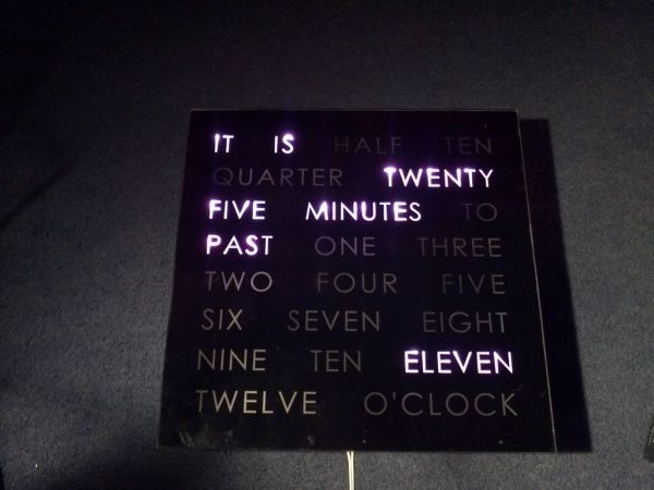
At long last I have managed to finish the Rainbow Word Clock!
Once again, this one was inspired by Doug and his creations http://www.instructables.com/id/The-Wordclock-Grew-Up/
I have a fixation with RGB LED’s at the moment and I wanted to do something a little different.
So, while it is still here (before my girlfriend nicks it!) I thought I would share the proccess with you.
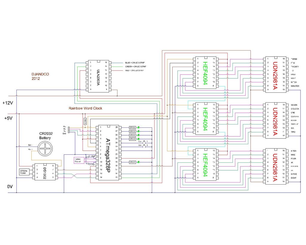
This is based on the Arduino ATmega328 with a slight redesign of the PCB to change the outputs from negative to positive and to add a ULN 2003 to handle the switching of the grounds.
Step 1: The design
I had a local company who do screen printing to make me two Word clock faces, one regular 300mm x 300mm and one custom 185mm x 205mm.
The smaller one is designed to be fitted into my cabinet just above the shelf, it has been sat in there for a number of months now happily telling me that I am late!
This one was also used as a test to do the first PCB, which turned out quite nice in the end.
Step 2: Building the body
The main part of the clock has not changed much from all of the others on this site.
I did make a few tweeks to try and improve the light spread without causing glare.
Key changes to the normal design are:
I used some plastic strips that I found at work and ripped them down to two sizes, a larger one for the outer frame and one smaller one for the internal shutters.
Once the grid is made I then covered it with reflective ducting tape, basically silver foil with a sticky back.
Placed the LED strips on the top and bottom of the cells so they are not glaring right at the word.
The LED strips were bought from eBay, 5M strips of RGB, but be careful though, some of the ones on sale say RGB but are actually three seporate LED’s, they don’t work half as good as the combined ones.
Step 3: Rainbow electronics
I have also added a PDF of the wiring diagram in the ZIP file.There are 4 wires from each LED strip, a switched positive, Blue Negative, Red negative and Green Nagative.
I connected all of the Red wires into a bunch with one more so I could connect it to the ribbon cable, the same with Green and Blue. I simply soldered the bunch together and then covered with heat shrink.
There is a small strip of breadboard to connect the ribbon cable to the white switched positve for each cell.
It is worth mapping the ribon cable out at this point with a 12V supply, make sure all of the LED’s work and note which wire does which cell.
 ATmega 328 pinout.pdf
- What inspired this project?
The project was inspired by Doug and his creations found on Instructables. - How did the author improve light spread?
The author covered the grid with reflective ducting tape and placed LED strips on the top and bottom of cells to avoid glare. - Which chip replaced the ULN2003 for switching grounds?
The UDN2981 chip was swapped in to handle the switching of the grounds. - Can I use any RGB LED strip from eBay?
No, some strips claim to be RGB but are actually three separate LEDs; combined ones work much better. - How many wires does each LED strip have?
There are four wires from each LED strip: a switched positive, Blue negative, Red negative, and Green negative. - What is the best way to connect the ribbon cable wires?
Solder all red wires together, all green wires together, and all blue wires together, then cover with heat shrink. - Does the new PCB design change the output polarity?
Yes, the PCB was redesigned to change the outputs from negative to positive. - What component drives the three PWM outputs for random colors?
A moved ULN2003 chip drives the three PWM outputs that generate random colors.