Summary of Create Animation on OLED Display Controlled by Arduino
This tutorial guides users in creating animations on a 128x32 OLED display using an Arduino Nano. It covers sourcing components, designing black-and-white bitmap frames, connecting hardware via SPI, and converting images to C code using the Image2cpp tool. The article details the necessary Arduino libraries, pin definitions, and code structure to loop through ten animation frames with 50ms delays for smooth playback.
Parts used in Create Animation on OLED Display Controlled by Arduino:
- Arduino Nano
- SSD1306 SPI 128x32 display
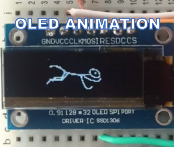
In this tutorial I will show you how to create animation on small OLED display connected to Arduino Nano.
Step 1: Supplies

We need following two components for this project
- Arduino Nano
- SSD1306 SPI 128×32 display
You can also use SSD1306SPI 128×32 display but it will need code adjustments when declaring the display.
Step 2: Creating Bitmaps for the Animation
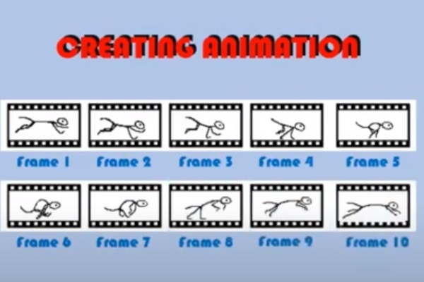
This is probably the most time consuming step. You have to create a set of frames thet would fit into 128×32 format. You can try to create them from any flipbook cliparts you can find on the net.
All the frames need to be black and white!!!
I created the frames that show the running creature
Step 3: Connectivity
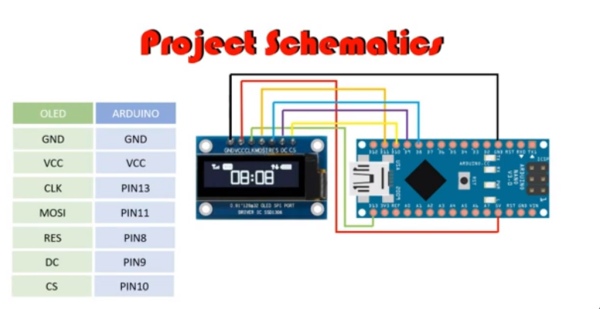
Here is the diagram how the OLED display should be connected to Arduino
If you are not familiar with OLED display you can also check my video tutorial on how to connect them and how to initialise them in Arduino code
Step 4: Creating Code Representation of the Bitmaps
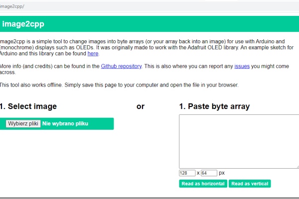
To create code representation of the bitmap we would use online tool
Image2cpp
You can find it going to the url below
https://javl.github.io/image2cpp/
Execute following steps:
- In Select Image section open your frame files one by one
- Check if images uploaded correctly by checking Image Settings section
- Check Invert image colors if you want to have black background and only line pixels lit
- In the Output section
- In Code Output Format specify “Arduino code”
- Provide the name of your animation in Identifier/Prefix
- Press Generate button
- Save the generated code . It will be pasted into arduino sketch
Step 5: Creating Animation Code
First we need to declare required libraries
#include <SPI.h>
#include <Wire.h>
#include <Adafruit_GFX.h>
#include <Adafruit_SSD1306.h><br>
First two are for SPI interface the other two are for working with OLED displays
The we need to define the size of the display
#define SCREEN_WIDTH 128 // OLED display width, in pixels
#define SCREEN_HEIGHT 32 // OLED display height, in pixels<br>
Then we declare pins through which OLED display is connected. And with those pinswe declare the display itself
// Declaration for SSD1306 display connected using software SPI
#define OLED_MOSI   11
#define OLED_CLK   13
#define OLED_DC    9
#define OLED_CS    10
#define OLED_RESET 8
Adafruit_SSD1306 display(SCREEN_WIDTH, SCREEN_HEIGHT,OLED_MOSI, OLED_CLK, OLED_DC, OLED_RESET, OLED_CS);<br>
Then you have to copy paste the code we got from Image2cpp
It is a fairly lengthy code so I will not paste it here in full. I will show just one frame
<strong> unsigned char RUN1 [] = {
  0x00, 0x00, 0x00, 0x00, 0x00, 0x00, 0x00, 0x00, 0x00, 0x00, 0x00, 0x00, 0x00, 0x00, 0x00, 0x00,
  0x00, 0x00, 0x00, 0x00, 0x00, 0x00, 0x00, 0x00, 0x00, 0x00, 0x00, 0x00, 0x00, 0x00, 0x00, 0x00,
  0x00, 0x00, 0x00, 0x00, 0x00, 0x00, 0x00, 0x00, 0x00, 0x00, 0x00, 0x00, 0x00, 0x00, 0x00, 0x00,
  0x00, 0x00, 0x00, 0x00, 0x00, 0x00, 0x00, 0x00, 0x00, 0x00, 0x00, 0x00, 0x00, 0x00, 0x00, 0x00,
  0x00, 0x00, 0x00, 0x00, 0x00, 0x00, 0x00, 0x00, 0x00, 0x00, 0x00, 0x00, 0x00, 0x00, 0x00, 0x00,
  0x00, 0xff, 0xc0, 0x00, 0x00, 0x00, 0x00, 0x00, 0x00, 0x00, 0x00, 0x00, 0xf8, 0x00, 0x00, 0x00,
  0x00, 0xfe, 0x00, 0x00, 0x00, 0x00, 0x1e, 0x00, 0x00, 0x00, 0x01, 0x83, 0x80, 0x00, 0x00, 0x00,
  0x07, 0x00, 0x00, 0x00, 0x03, 0x00, 0xc0, 0x00, 0x00, 0x00, 0x01, 0xc0, 0x00, 0x00, 0x03, 0x0c,
  0x40, 0x00, 0x00, 0x00, 0x00, 0xff, 0xff, 0xff, 0xe1, 0x0c, 0x60, 0x00, 0x00, 0x00, 0x00, 0xf0,
  0x00, 0x1f, 0xff, 0x80, 0x20, 0x00, 0x00, 0x00, 0x01, 0xe0, 0x00, 0x01, 0xf9, 0xe0, 0x20, 0x00,
  0x00, 0x00, 0x03, 0xc0, 0x00, 0x00, 0xcc, 0x78, 0x60, 0x00, 0x00, 0x03, 0xe7, 0x80, 0x00, 0x00,
  0x64, 0x1f, 0xc0, 0x00, 0x00, 0x0e, 0xff, 0x00, 0x00, 0x00, 0x66, 0x00, 0x00, 0x00, 0x00, 0x1c,
  0x0e, 0x00, 0x00, 0x00, 0x33, 0xf0, 0x00, 0x00, 0x00, 0x30, 0xf8, 0x00, 0x00, 0x00, 0x18, 0x1f,
  0xf0, 0x00, 0x00, 0x7f, 0xf0, 0x00, 0x00, 0x00, 0x08, 0x00, 0x00, 0x00, 0x01, 0xfc, 0x00, 0x00,
  0x00, 0x00, 0x0c, 0x00, 0x00, 0x00, 0x03, 0x80, 0x00, 0x00, 0x00, 0x00, 0x06, 0x00, 0x00, 0x00,
  0x07, 0x00, 0x00, 0x00, 0x00, 0x00, 0x03, 0x00, 0x00, 0x00, 0x0e, 0x00, 0x00, 0x00, 0x00, 0x00,
  0x01, 0x86, 0x00, 0x00, 0x0c, 0x00, 0x00, 0x00, 0x00, 0x00, 0x00, 0xcc, 0x00, 0x00, 0x00, 0x00,
  0x00, 0x00, 0x00, 0x00, 0x00, 0x78, 0x00, 0x00, 0x00, 0x00, 0x00, 0x00, 0x00, 0x00, 0x00, 0x00,
  0x00, 0x00, 0x00, 0x00, 0x00, 0x00, 0x00, 0x00, 0x00, 0x00, 0x00, 0x00, 0x00, 0x00, 0x00, 0x00,
  0x00, 0x00, 0x00, 0x00, 0x00, 0x00, 0x00, 0x00, 0x00, 0x00, 0x00, 0x00, 0x00, 0x00, 0x00, 0x00
};<br></strong>
Then in Setup function we are initialising the OLED display
void setup() {

  // SSD1306_SWITCHCAPVCC = generate display voltage from 3.3V internally
  if(!display.begin(SSD1306_SWITCHCAPVCC)) {
    Serial.println(F("SSD1306 allocation failed"));
    for(;;); // Don't proceed, loop forever
  }

  // Show initial display buffer contents on the screen --
  // the library initializes this with an Adafruit splash screen.
  display.display();
  delay(2000); // Pause for 2 seconds
}<br>
And then we have loop functions where we replay all 10 frames in 50ms intervals
void loop() {

  // Diplay Animation

  // Frame1
  display.clearDisplay();
  display.drawBitmap(30,0,RUN1, 80, 32, 1);
  display.display();
  delay(50);

  // Frame2
  display.clearDisplay();
  display.drawBitmap(30,0,RUN2, 80, 32, 1);
  display.display();
  delay(50);

  // Frame3
  display.clearDisplay();
  display.drawBitmap(30,0,RUN3, 80, 32, 1);
  display.display();
  delay(50);

  // Frame4
  display.clearDisplay();
  display.drawBitmap(30,0,RUN4, 80, 32, 1);
  display.display();
  delay(50);

  // Frame5
  display.clearDisplay();
  display.drawBitmap(30,0,RUN5, 80, 32, 1);
  display.display();
  delay(50);

  // Frame6
  display.clearDisplay();
  display.drawBitmap(30,0,RUN6, 80, 32, 1);
  display.display();
  delay(50);

  // Frame7
  display.clearDisplay();
  display.drawBitmap(30,0,RUN7, 80, 32, 1);
  display.display();
  delay(50);

  // Frame8
  display.clearDisplay();
  display.drawBitmap(30,0,RUN8, 80, 32, 1);
  display.display();
  delay(50);

  // Frame9
  display.clearDisplay();
  display.drawBitmap(30,0,RUN9, 80, 32, 1);
  display.display();
  delay(50);

  // Frame10
  display.clearDisplay();
  display.drawBitmap(30,0,RUN10, 80, 32, 1);
  display.display();
  delay(50); <br>
You can get the entire code going to following URL
Step 6: Final Result
You can see the final result in the attached video tutorial.
This particular animation was done for fun. But also please check my other video in which I create animation for a real project. Here I build an eggtimer/countdown timer in which when the counter goes down to zero the buzzer sound is played. I added a ringing bell animation to go with the buzzer sound.
Hope you enjoyed this tutorial and you will be able to replay my animation.
It would be great if you could based on this tutorial create your own animation. If you do don’t forget to send me the links to videos that will show the result of your work.
If you like this content and you want to support me in creating similar videos go to my Patreon webpage
https://www.patreon.com/MariosIdeas Or Paypal
Source: Create Animation on OLED Display Controlled by Arduino
- What components are required for this project?
You need an Arduino Nano and an SSD1306 SPI 128x32 display. - Can I use an alternative display model?
Yes, you can use an SSD1306 SPI 128x32 display, but it requires code adjustments when declaring the display. - What color format must the animation frames be?
All frames must be created in black and white. - Which online tool converts bitmaps to Arduino code?
The tool Image2cpp is used to create the code representation of the bitmaps. - How do I specify the output format in Image2cpp?
In the Output section, you must specify "Arduino code" in the Code Output Format field. - Which libraries are required for the Arduino sketch?
You need to include SPI.h, Wire.h, Adafruit_GFX.h, and Adafruit_SSD1306.h. - At what interval are the animation frames displayed?
The code replays all 10 frames at 50ms intervals. - How many frames are included in the example animation?
The example loops through 10 distinct frames labeled RUN1 through RUN10.