Summary of Quiz Game Controller using “Lights and Sounds Buzzers” and Arduino
YAQGC (Yet Another Quiz Game Controller) uses modified Learning Resources Lights and Sounds Buzzers and an Arduino Uno to implement a Jeopardy-style first-to-respond lockout system that records 1st–4th places. Each buzzer is rewired with a 2.5mm stereo jack and a compact reed relay so the Arduino can read button presses and control lights and sounds independently. The control box houses the Arduino, reset button, and four LEDs. Intermediate soldering and careful PCB trace cuts are required; the system supports configurable game modes and timings.
Parts used in the YAQGC (Yet Another Quiz Game Controller):
- 4x Lights and Sounds Buzzers by Learning Resources
- 4x Submini (2.5mm) stereo phone jacks
- 4x Mini Reed Relays (e.g., Radio Shack 275-0232 or similar)
- 1x Arduino Uno
- 1x Project Box
- 4x LEDs (Red, Blue, Green, Yellow) with resistors or similar
- 5x resistors, 2.2K (or values from 220 to 2.2K)
- 8x 2.5mm stereo mini phone jacks (note: parts list mentions 4 and 8 in places)
- 1x Reset Button, Normally Open, Momentary Contact (e.g., RS 275-609 or similar)
- 2x 3 ft 2.5mm Male to 2.5mm Male stereo cables
- 2x 6 ft 2.5mm Male to 2.5mm Male stereo cables
- Hookup wire
- Tools: soldering iron, Phillips and flathead screwdrivers, Dremel or rotary tool
- Computer to load the Arduino code
Jeopardy style quiz games are favorites for creating excitement and educational instruction at the same time. Teachers, summer camp counselors, and even industry educators find this type of game to help generate interest and involvement from the participants.
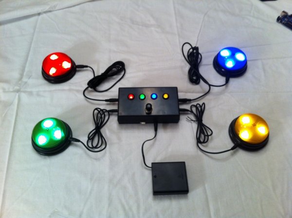
The idea behind the game is simple, but sometimes finding a device that will perform the “first to respond” lockout function can be problematic. Here is YAQGC (Yet Another Quiz Game Controller 🙂 based on some pretty neat lighted buzzers and an Arduino put in to a project box.
While the “Lights and Sounds Buttons” from Learning Resources were designed as “stand alone” devices, a few modifications allows them to be connected to and controlled by an Arduino controller. The “Lights and Sounds Buzzers” make a professional looking and fun implementation of a Quiz Game controller.
The buzzers are modified to plug into a base unit and provide “button press” signals and accept an “activation” signal.
The control box houses the Arduino Uno, the reset button, and four LEDs.
While the button modifications are a little tedious, intermediate soldering skills and patience will produce a nice looking and fun to use Quiz Game Controller.
In addition to capturing the first to respond “winner”, the controller also captures 2nd, 3rd, and 4th place in order of button press. The order is indicated on the control box LEDs. Of course the beauty of having a programmable controller is tuning it to just the way you want it. Other game modes are possible, including “Wheel of Fortune” modes, although this version of the Arduino program only implements the “Jeopardy” style game.
Let’s get started!
YouTube demo of completed system
Background and instructions on www.projectnotions.com
Step 2: Button Modifications
Overview
The button is modified to accomplish three functions: * First, to bring to the control box a line when the button is pressed. * Second, to bring a line from the control box to the button to turn on the lights and sound. * Third, provide a relay that allows the sound to be turned off.
Because there are 4 things we want to do (ground, button press, activate lights, activate sound) and we only have 3 wires, we have to combing two functions using one wire. We accomplish this by taking advantage that the logic on the button does it’s own management of the lights and sounds function. When the “activate” line goes high for about 20ms the button logic activates the light and sound. By connecting a compact relay to this same line we can control the sound in an independent way.
Here are the states we manage on the “activate” line.
– Low – The button is off. If it was previously activated, it will turn itself off after about 2.5 to 3 seconds.
High Pulse – We drive the activate button high for 20ms, and then drive it low again. The button logic will turn on the lights and sound for 2.5 to 3 seconds, but because we connected the speaker through the relay, the relay will only stay on for 20ms. So, we don’t really hear any sound because the relay has disconnected the speaker from the circuit.-
– High Solid – We drive the activate button high for about 2.5 seconds. The relay keeps the speaker connected to the circuit for the entire duration of the button’s “activation time.” and we both see the lights AND heard the sound.
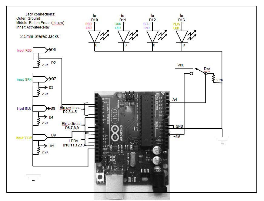
The button schematic is below.
With these modifications we can program the Arduino to mange the lights and sounds independently. Our initial program turned both lights and sounds on for the first cycle, and then just turned the lights on over and over again until the reset button was pressed or until the timeout expired.
It is somewhat of a tight fit in the button and we chose a 2.5mm stereo phone jack for the connector to minimize the space required. The four main changes are:
Cut the pc board trace to separate the “button press” signal from the “activation line.”
Drill a hole, countersink it, and mount the phone jack.
Mount the compact relay.
Cut and solder the necessary wires.
Step by step instructions:
1. Collect the parts
4x Lights and Sounds Buzzers
4x Submini phone Jacks
4x Reed relays
Hookup wire
2. Disassemble the buttons
Remove the four feet from the bottom (A small flathead screwdriver might help.)
Remove the four screws
Remove the battery compartment cover
Repeat for each button
Components
Here are the required parts:
– (quantity) Description
– (1) Set of “Lights and Sounds Buzzers” by Learning Resources
– (4) Mini Reed Relays (Radio Shack 275-0232 or similar)
– (1) Arduino Uno
– (1) Project Box
– (4) LEDs, one each in Red, Blue, Green, Yellow (with included resistor or similar)
– (5) resistors, 2.2K (RS 275-1301 or similar) (or any value you have from 220 to 2.2K should work)
– (8) 2.5mm stereo mini phone jacks
– (1) Reset Button, Normally Open, Momentary Contact (RS 275-609 or similar)
– (2) 3 feet 2.5mm Male To 2.5mm Male – Stereo
– (2) 6 feet 2.5mm Male To 2.5mm Male – Stereo
– (1) Project Box
– hookup wire
Tools include:
– Soldering iron
– screwdrivers (phillips and flat head)
– Dremel type tool for cutting and countersinking holes
– (computer to load the Arduino code)
For more detail: Quiz Game Controller using “Lights and Sounds Buzzers” and Arduino
- What is YAQGC?
YAQGC is Yet Another Quiz Game Controller that uses modified Lights and Sounds Buzzers and an Arduino to implement a Jeopardy-style first-to-respond system recording 1st–4th places. - How are the Learning Resources buzzers modified?
The buzzers are cut to separate the button press trace, fitted with a 2.5mm stereo phone jack, wired to a compact reed relay, and have wires soldered to provide ground, button press, activate lights, and activate sound functions. - How does the activate line behavior work?
The activate line can be driven low, pulsed high for ~20ms to activate lights briefly while relay disconnects sound, or driven high solid for ~2.5 seconds to keep lights and sound on via the relay. - What does the control box contain?
The control box houses the Arduino Uno, the reset button, and four LEDs indicating the order of responses. - Can the controller record multiple places?
Yes, the controller captures 1st, 2nd, 3rd, and 4th places in order of button presses and indicates order with the control box LEDs. - What skill level is required to modify the buttons?
Intermediate soldering skills and patience are recommended because the button modifications are somewhat tedious and tight-fitting. - Why is a relay used in the button modification?
A compact relay is used on the activate line to independently control the speaker so the Arduino can manage lights and sounds separately. - What connector size was chosen and why?
A 2.5mm stereo phone jack was chosen to minimize space required inside the button housing.