Summary of Audio Input to Arduino
Summary: This article explains methods to connect audio signals to an Arduino: a simple three-component passive input (two resistors and a capacitor) and a higher-sensitivity option using an amplifier (NE5532-based Super Ear Amplifier kit or SparkFun electret microphone breakout). It warns against replacing NE5532 with LM358/LM324 due to frequency response, shows how to speed up the ATmega328 ADC via ADCSRA and ADMUX settings, and demonstrates sampling via Timer1 ISR storing data for FFT processing. It also mentions using spare USB speakers to avoid soldering.
Parts used in the Super Ear Amplifier Kit:
- NE5532 Operational Amplifier IC
- Printed circuit board (included in kit)
- Resistors (as per amplifier circuit)
- Capacitors (as per amplifier circuit)
- Electret microphone (when used with breakout)
- SparkFun Electret Microphone Breakout (alternative option)
- Arduino (ATmega328 based)
- TimerOne library (software component for sampling)
- USB speakers (optional spare to avoid soldering)
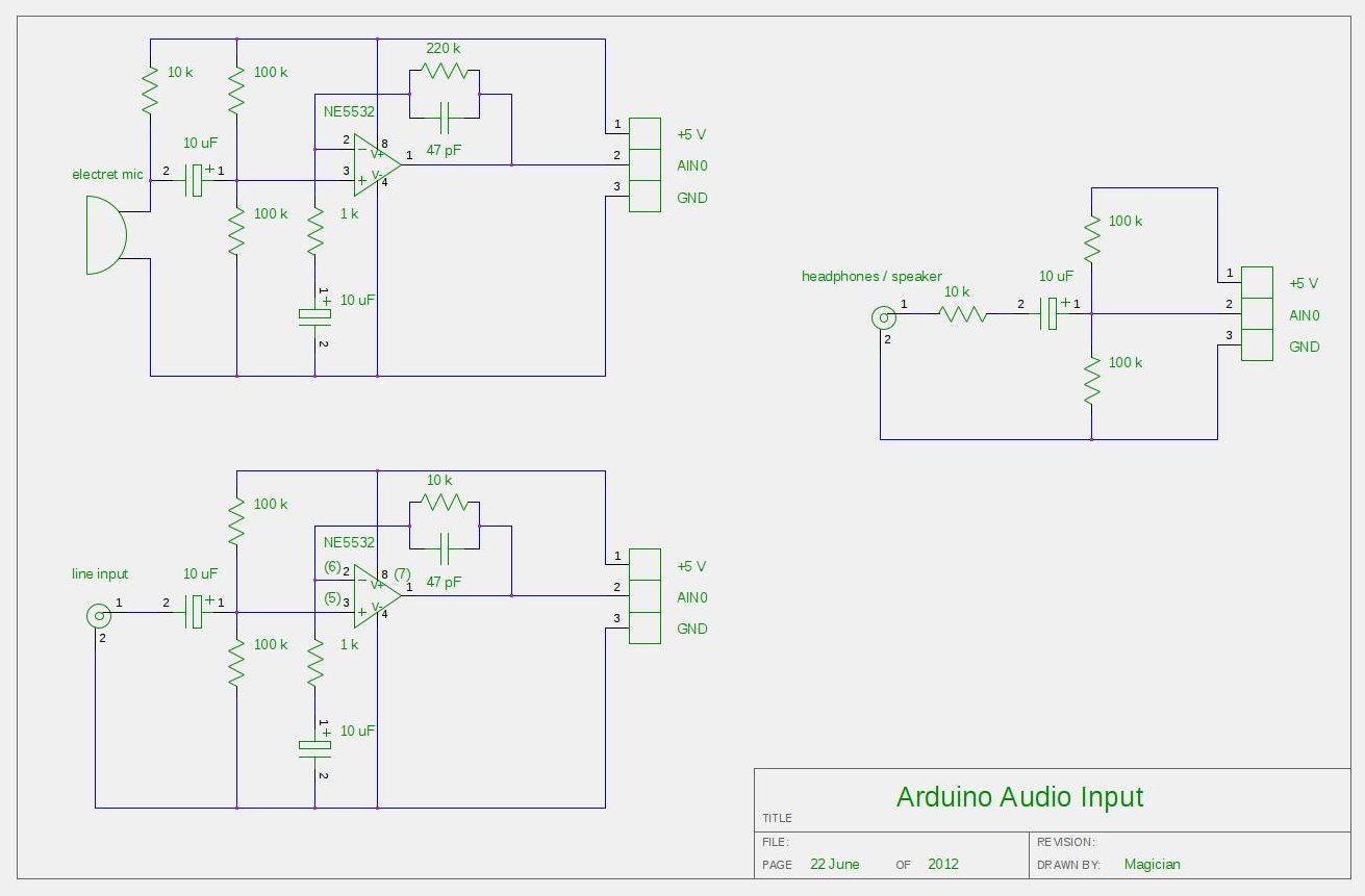
The easiest way to connect an audio signal to your arduino, is to build a simple 3 components (2 resistors plus cap) circuitry shown on the first drawings on right side. Disadvantage: there is no amplifier, and consequently sensitivity would be low, hardly enough to work with headphones jack output. For low level signals, like output of electret microphone, amplifier is necessary. Here is the kit, which included board, electronic components and NE5532 Operational Amplifier IC:
Super Ear Amplifier Kit
Other option, from SparkFun Electronics:
Breakout Board for Electret Microphone
Note: I don’t recommend to replace NE5532 OPA with popular LM358 or LM324 due their pure frequency response above > 10 kHz.
Configuring AtMega328 ADC to take input samples faster:
void setup() {
ADCSRA = 0×87; // freq = 1/128, 125 kHz. 13 cycles x 8 usec = 104 usec.
// ADCSRA = 0×86; // freq = 1/64, 250 kHz. 13 cycles x 4 usec = 52 usec.
// ADCSRA = 0×85; // freq = 1/32, 500 kHz. 13 cycles x 2 usec = 26 usec.
// ADCSRA = 0×84; // freq = 1/16 , 1 MHz. 13 cycles x 1 usec = 13 usec.
// ADCSRA = 0×83; // freq = 1/8, 2 MHz. 13 cycles x 0.5 usec = 6.5 usec.
// ADCSRA = 0×82; // freq = 1/4, 4 MHz. 13 cycles x 0.25 usec = 3.25 usec.
ADMUX = 0×40; // Select Analog Input 0
ADCSRA |= (1<<ADSC); // Start Conversion
Timer1.initialize(T_PERIOD); // Sampling with TimerOne library
Timer1.attachInterrupt(iProcess);
}
Reading and storing samples to array via ISR ( Timer Interrupt Subroutine ), Timer1 in this example:
void iProcess()
{
static uint8_t n_sampl;
if (ADCSRA & 0×10)
{
int16_t temp = ADCL;
temp += (ADCH << 8);
temp -= sdvigDC;
ADCSRA |= (1<<ADSC);
xin[n_sampl] = temp;
}
if (++n_sampl >= FFT_SIZE )
{
n_sampl = 0;
process = 1;
}
}
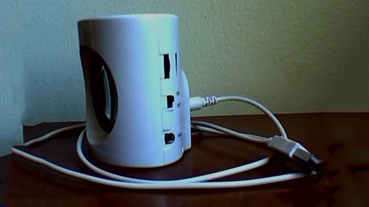
Don’t like to solder all this components from the drawings above? Here is easy way around, if you, by chance, have a spare USB speakers. Something like this:
For more detail: Audio Input to Arduino
- What is the simplest circuit to connect audio to an Arduino?
A simple three-component circuit of two resistors and one capacitor is the easiest way described in the article. - Is an amplifier necessary for low level signals like electret microphones?
Yes, for low level signals such as electret microphone outputs, an amplifier is necessary according to the article. - Which operational amplifier IC does the kit include?
The kit includes the NE5532 operational amplifier IC. - Can I replace NE5532 with LM358 or LM324?
The article does not recommend replacing NE5532 with LM358 or LM324 due to their frequency response above 10 kHz. - How can I increase ADC sampling speed on ATmega328?
By setting ADCSRA to values like 0x87, 0x86, 0x85, etc., and configuring ADMUX, you can increase ADC sampling speed as shown in the article. - How are ADC samples read and stored in this project?
ADC samples are read in an ISR triggered by Timer1; ADCL and ADCH are combined into a 16-bit value, DC offset is subtracted, and samples are stored into an array until FFT_SIZE is reached. - Is there a way to avoid soldering components for audio input?
Yes, the article suggests using a spare USB speaker as an easy way to avoid soldering the components. - What library is used for timer-based sampling?
The TimerOne library is used for timer-based sampling in the example.