
Summary of GSM Home Security Alarm System with Arduino
This article details a theft control system for homes using an Arduino Uno microcontroller and a SIM900A GSM modem. The system detects intrusions via sensors connected to input J2, sending SMS alerts or initiating call alerts to pre-configured numbers. It features active-low triggers for SMS messages, call initiation, and call termination, powered by a 12VDC source.
Parts used in the Home Theft Control System:
- Arduino Uno microcontroller
- SIM900A based GSM/GPRS modem
- 12VDC/2A power supply unit or battery
- Intrusion-detector unit (e.g., light fence or motion sensor)
- Connector J2 for sensor input
- Push button switch S2 for call alert
- Push button switch S3 for ending calls
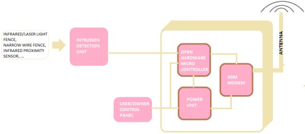
This project deals with the design & development of a theft control system for home, which is being used to prevent/control any theft attempt. The developed system makes use of an embedded system (comprises an open hardware microcontroller and a gsm modem) based on Global System for Mobile communication (GSM) technology.
The designed & developed system can be installed in the home. An interfacing intrusion-detector unit is also connected to the microcontroller-based security system.
In case of an intrusion attempt, a warning message is being transmitted by the system (as an sms) to the owner’s mobile phone, or to any pre-configured mobile phone number for further processing.
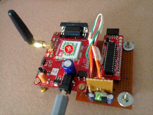 The security system comprises of an Arduino Uno microcontroller and a standard SIM900A based GSM/GPRS modem. The whole system can be powered from any 12VDC/2A power supply unit/battery.
System diagram of the security system is shown here.
Working of the system is very simple and self-explanatory. When input power is applied to the system, the system goes into standby mode. However, when the terminals of connector J2 is short circuited, the preprogrammed warning message is automatically transmitted to the concerened mobile number. You can connect any intrusion detection unit (such as a light fence or a motion sensor) to the input connector J2. Note that an active-low (L) at pin 1 of connector J2 triggers the security system.
Further, an optional “call – alert” facility is added to the security system, which will initiate a telephone call when push button switch S2 is activated by the user (or by another electronic module). After the “call” key (S2) operation, the call can be aborted by depressing the second push button switch S3 – the “end” key. This option can be used to make a “missed call” alert, incase of an intrusion attempt.
The circuit is highly-flexible so that you can use any SIM900A modem (and ofcourse any Arduino Uno board) of your choice. Carefully read the modem documentation before construction to make the task sweet and simple.
Arduino Sketch:
- /*
- * Arduino Home Security GSM Alarm
- * An Arduino + SIM900A Project
- * T.K.Hareendran
- * Tested at TechNode PROTOLABZ
- * 21 August 2014
- * http:// www.electroschematics.com
- */
- //Connect the Tx pin of the GSM modem to D3
- //Connect the Rx pin of the GSM modem to D4
- //SMS Trigger Key/Input connected to D7 (Active LOW)
- //CALL Trigger Key connected to D8 (Active LOW)
- //END Key Connected to D9 (Active LOW)
- #include <NewSoftSerial.h>
- NewSoftSerial mySerial(3,4); // RX and TX pins to communicate with GSM module
- #define msg_key 7
- #define call_key 8
- #define end_key 9
- String number =”0000000000″; // Add the 10-Digit Mobile Number to which message / call is to be made,by replacing the 0’s
- void setup()
- {
- Serial.begin(9600);
- mySerial.begin(9600);
- pinMode(msg_key,INPUT);
- pinMode(call_key,INPUT);
- pinMode(end_key,INPUT);
- digitalWrite(msg_key,HIGH);
- digitalWrite(call_key,HIGH);
- digitalWrite(end_key,HIGH);
- }
- void loop()
- {
- //Sends an sms everytime msg_key is pressed
- if (digitalRead(msg_key)==LOW) // Check if the sms key is being pressed
- {
- mySerial.println(“AT+CMGF=1”); // Set the Mode as Text Mode
- delay(150);
- mySerial.println(“AT+CMGS=\”+00″+number+”\””); // Specify the Destination number in international format by replacing the 0’s
- delay(150);
- mySerial.print(“Warning! Intruder Alert!”); // Enter the message
- delay(150);
- mySerial.write((byte)0x1A); // End of message character 0x1A : Equivalent to Ctrl+z
- delay(50);
- mySerial.println();
- }
- //Makes a call when call_key is pressed
- else if (digitalRead(call_key)==LOW) // Check if the call key is being pressed
- {
- mySerial.println(“ATD+91″+number+”;”); //Specify the number to call
- while(digitalRead(call_key)==LOW);
- delay(50);
- }
- //Hang the call
- else if (digitalRead(end_key)==LOW) // Check if the hang up key is being pressed
- {
- mySerial.println(“ATH”);
- while(digitalRead(end_key)==LOW);
- delay(50);
- }
- }
If you are a newcomer in Arduino world, it is recommended to refer related tutorials and projects available elsewhere in this website!
For more detail: GSM Home Security Alarm System with Arduino
- How does the system send alerts?
The system transmits a warning message as an SMS to the owner's mobile phone or any pre-configured number when an intrusion attempt is detected. - What triggers the security system?
An active-low signal at pin 1 of connector J2 triggers the system, which can be activated by shorting terminals or connecting an intrusion detector. - Can users make a missed call alert?
Yes, an optional call-alert facility initiates a telephone call when push button switch S2 is activated. - How do you end an initiated call?
The call can be aborted by depressing the second push button switch S3, which acts as the end key. - What components are required for the circuit?
The circuit requires an Arduino Uno board and any SIM900A modem of your choice. - What power supply does the system need?
The whole system is powered from any 12VDC/2A power supply unit or battery. - Which pins connect the GSM modem to the Arduino?
The Tx pin of the GSM modem connects to D3, and the Rx pin connects to D4 on the Arduino. - How is the destination number configured?
The user must replace the zeros in the code string with their specific 10-digit mobile number to receive messages or calls.
