Summary of DIY Self Balancing Robot using Arduino
Summary: This guide documents building a two-wheeled self-balancing robot using Arduino UNO, MPU6050 sensor, DC geared motors, L298N driver, 7.4V battery, PID control, and a 3D-printed chassis. It covers parts selection, wiring, MPU6050 DMP setup, PID tuning, motor control code, assembly tips, and testing procedures to stabilize the robot by reading yaw/pitch/roll and adjusting wheel motion.
Parts used in the Self Balancing Robot:
- Arduino UNO
- Geared DC motors (yellow coloured) – 2 Nos
- L298N Motor Driver Module
- MPU6050 (accelerometer and gyroscope)
- A pair of wheels
- 7.4V Li-ion battery
- Connecting wires
- 3D printed body / chassis
- 3mm bolts and nuts
- Perf board (for final wiring)
After seeing RYNO motors and Segway’s self balancing scooters, I was always interested in creating something alike. After some consideration, I made the decision to create a Self Balancing Robot using Arduino. This way, I would understand the fundamental idea behind the scooters and also gain knowledge of how the PID algorithm operates.
As soon as I began constructing, I understood that constructing this robot would be quite a challenging task. There are numerous choices available, leading to confusion beginning with selecting the motors and continuing throughout the process of tuning PID values. There are numerous factors to take into account such as battery type, battery placement, wheel traction, motor driver type, maintaining the Centre of Gravity, and many others.
However, once you construct it, you will realize that it is not as difficult as it may seem. Let’s be honest, in this guide I will detail my journey of creating the self-balancing robot. You could be a complete novice taking the first steps or have arrived here after struggling for a while with your bot not functioning. This location is striving to be your ultimate stop. Let’s begin now……
Selecting the Parts for your Bot
Before I tell you all the options for building the bot let me list the items that I have used in this project
- Arduino UNO
- Geared DC motors (Yellow coloured) – 2Nos
- L298N Motor Driver Module
- MPU6050
- A pair of wheels
- 7.4V Li-ion Battery
- Connecting wires
- 3D Printed Body
Controller: I chose to use Arduino UNO as the controller here because it is user-friendly and simple to work with. You could opt for an Arduino Nano or Arduino mini, however, I suggest sticking with the UNO as we can program it without needing any additional hardware.
Motors: The top motor option for a self balancing robot is definitely the Stepper motor. However, for simplicity’s sake, I opted for a DC gear motor. No, having a stepper motor is not required; the bot functions well with these affordable yellow DC gear motors that are readily available.
Motor Driver: If you have selected the DC gear motors like mine then you can either use the L298N driver module like me, or even a L293D should work just fine. Learn more about controlling DC motor using L293D and Arduino.
Wheels: Do not under estimate these guys; I had a tough time figuring out that the problem was with my wheels. So make sure your wheels have good grip over the floor you are using. Watch closely, your grip should never allow your wheels to skit on the floor.
Accelerometer and Gyroscope: The best choice of Accelerometer and Gyroscope for your bot will be the MPU6050. So do not attempt to build one with a normal Accelerometer like ADXL345 or something like that, it just won’t work. You will know why at the end of this article. You can also check our dedicated article on using MPU6050 with Arduino.
Battery: We need a battery that is as light as possible and the operating voltage should be more than 5V so that we can power our Arduino directly without a boost module. So the ideal choice will be a 7.4V Li-polymer battery. Here, since I had a 7.4V Li-ion battery readily available I have used it. But remember a Li-po is advantageous than Li-ion.
Chassis: Another area where you should not make concessions is regarding your bots frame. You are able to utilize cardboard, wood, plastic, or any material you are comfortable with. However, ensure that the chassis is strong and does not move when the robot is attempting to maintain balance. I created my own chassis using Solidworks, taking inspiration from other bots, and then 3D printed it. Having a printer allows you to print the design files that will be included in the next section.
3D Printing and Assembling the Bot
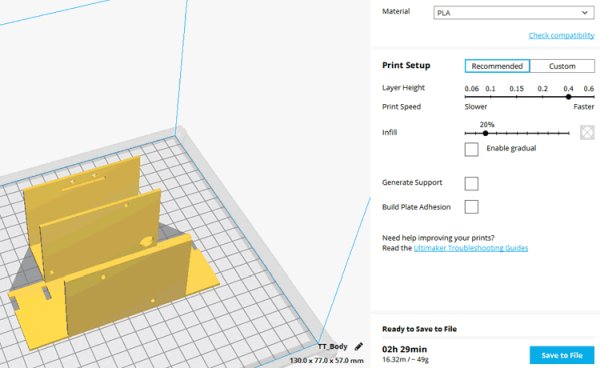
If you have decided to 3D print the same chassis that I am using to build my bot, then the STL files can be downloaded from thingiverse. I have also added the design files along with it so you can also modify it as per your personnel preferences.
The parts have no overhanging structures so you can easily print them without any supports and an infill of 25% will work fine. The designs are pretty plain and any basic printer should be able to handle it with ease. I used the Cura software to slice the model and printed using my Tevo Tarantula, the setting are shown below.
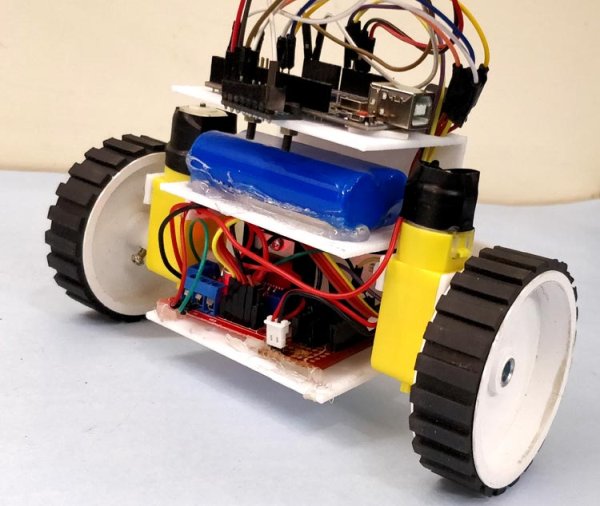
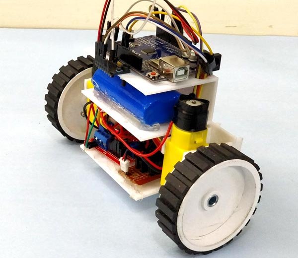
To make, you must print the body section and also four parts for mounting the motors. Putting together the items is quite simple; utilize 3mm bolts and nuts to fasten the motor and boards down. Once put together, it should resemble the image depicted below.
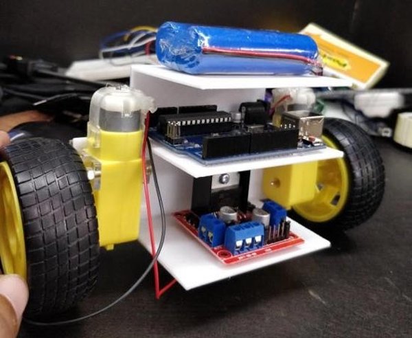
The current layout included placement of the L298N drive module in the lower shelf and the Arduino and battery on top, as depicted in the image. If you are sticking to the same sequence, you can fasten the board through the pre-made holes and attach a wire tag to the Li-po battery. This setup should function as well, apart from the very basic wheels that I replaced afterwards.
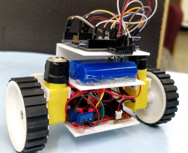
I rearranged the battery and Arduino UNO board in my bot to simplify programming, and added a perf board to finalize the connections. My bot didn’t appear as I envisioned during the first phase. After finishing the wiring, programming, and testing, my bot now appears like this.
Circuit Diagram
Making the connections for this Arduino based Self balancing Robot is pretty simple. We just have to interface the MPU6050 with Arduino and connect the motors though the Motor driver module. The whole set-up is powered by the 7.4V li-ion battery. The circuit diagram for the same is shown below.
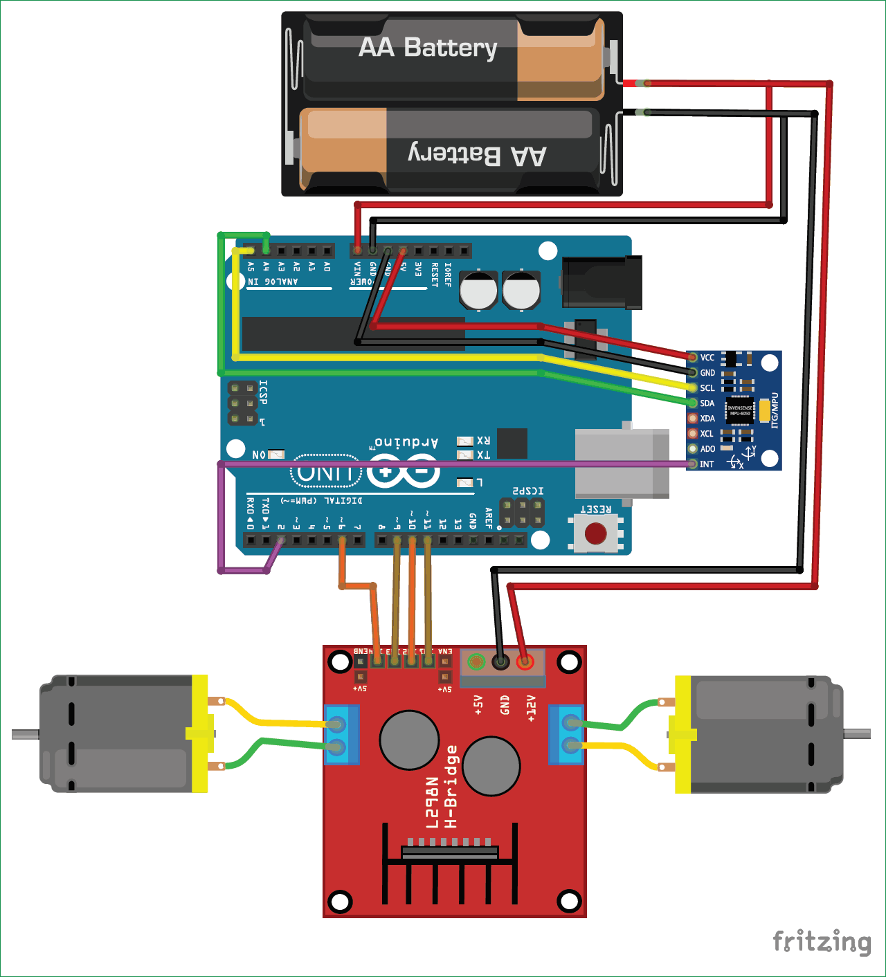
The Vin pin powers the Arduino while the 12V terminal powers the L298N Motor driver module. The Arduino board’s built-in regulator will change the input voltage from 7.4V to 5V to supply power to the ATmega IC and MPU6050. The DC motors can operate within a voltage range of 5V to 12V. However, we will be linking the 7.4V positive cable from the battery to the 12V input terminal of the motor driver module. The motors will function at a voltage of 7.4V. The subsequent table will outline the connection between the MPU6050 and L298N motor driver module with Arduino.
| Component Pin | Arduino Pin |
| MPU6050 | |
| Vcc | +5V |
| Ground | Gnd |
| SCL | A5 |
| SDA | A4 |
| INT | D2 |
| L298N | |
| IN1 | D6 |
| IN2 | D9 |
| IN3 | D10 |
| IN4 | D11 |
The communication between Arduino and MPU6050 is established via the I2C interface, therefore we utilize Arduino’s A4 and A5 pins designated for SPI communication. The DC motors are linked to PWM pins D6, D9, D10, and D11 in that order. We have to link them to PWM pins as we will adjust the DC motor’s speed by changing the duty cycle of the PWM signals. If you are unfamiliar with these two parts, it is advisable to go through the MPU6050 Interfacing and L298N Motor driver tutorial.
Programming the Self Balancing Robot
Next, we need to code our Arduino UNO board in order to stabilize the robot. This is the place where all the magic occurs; the idea behind it is straightforward. We need to determine if the bot is tilting forward or backward with the help of the MPU6050. If it’s leaning forward, we should turn the wheels forward, and if it’s leaning backward, we should turn the wheels backwards.
We must also manage the rotation speed of the wheels while ensuring the bot stays centered; the wheels rotate slowly when slightly off-centered and increase in speed as the bot moves further away from the center position. The PID algorithm is utilized to achieve this logic, with the center position as the set-point and the degree of disorientation as the output.
We utilize the MPU6050, a sensor that combines a 6-axis accelerometer and gyroscope, to determine the bot’s current location. To obtain an accurate position measurement from the sensor, it is necessary to combine data from both the accelerometer and gyroscope. The accelerometer data may have noise issues, while the gyroscope data tends to drift over time. We need to combine both values to determine the yaw, pitch, and roll of our robot, but we will only use the yaw value.
Doesn’t it make your head spin a little? However, do not be concerned, because the Arduino community provides libraries that can easily handle the PID calculation and extract the yaw value from the MPU6050. The library is created by br3ttb and jrowberg individually.
Now that we have included the libraries in our Arduino IDE. We should begin coding for our Self balancing Robot. As usual, the full code for the Project can be found at the bottom of this page, where I will only be discussing the key sections in the code. Previously, it was mentioned that the code is based on the MPU6050 example code. We will simply enhance the code for our specific requirements and incorporate PID and control techniques for our self-balancing robot.
Initially, we add the necessary libraries for the program to function properly. This includes the built-in I2C library, PID Library, and MPU6050 Library that was recently downloaded.
#include “I2Cdev.h”
#include <PID_v1.h> //From https://github.com/br3ttb/Arduino-PID-Library/blob/master/PID_v1.h
#include “MPU6050_6Axis_MotionApps20.h” //https://github.com/jrowberg/i2cdevlib/tree/master/Arduino/MPU6050
Then we declare the variables that are required to get the data from the MPU6050 sensor. We read both the gravity vector and quaternion values and then compute the yaw pitch and roll value of the bot. The float array ypr[3] will hold the final result.
// MPU control/status vars
bool dmpReady = false; // set true if DMP init was successful
uint8_t mpuIntStatus; // holds actual interrupt status byte from MPU
uint8_t devStatus; // return status after each device operation (0 = success, !0 = error)
uint16_t packetSize; // expected DMP packet size (default is 42 bytes)
uint16_t fifoCount; // count of all bytes currently in FIFO
uint8_t fifoBuffer[64]; // FIFO storage buffer
// orientation/motion vars
Quaternion q; // [w, x, y, z] quaternion container
VectorFloat gravity; // [x, y, z] gravity vector
float ypr[3]; // [yaw, pitch, roll] yaw/pitch/roll container and gravity vector
Following is the highly significant part of the code, where you will dedicate a substantial amount of time adjusting for the correct values. If your robot is well-balanced and has symmetrical components (which is usually not the case), the set-point value will be 180. Alternatively, you can connect your bot to the Arduino serial monitor and adjust its tilt until you reach a stable position. Take note of the value shown on the serial monitor, as this will be your set point value. The tuning of Kp, Kd, and Ki should match your bot’s characteristics. There is no way to avoid it as no two identical bots will have matching values for Kp, Kd, and Ki. View the video located at the bottom of this page for guidance on adjusting these values.
/*********Tune these 4 values for your BOT*********/
double setpoint= 176; //set the value when the bot is perpendicular to ground using serial monitor.
//Read the project documentation on circuitdigest.com to learn how to set these values
double Kp = 21; //Set this first
double Kd = 0.8; //Set this secound
double Ki = 140; //Finally set this
/******End of values setting*********/
In the following line, we start the PID algorithm by providing the input variables input, output, set point, Kp, Ki, and Kd. In the above section of code, we have already specified the values for set-point Kp, Ki, and Kd. The input value will be the current yaw value from the MPU6050 sensor, and the output value will be the result calculated by the PID algorithm. In essence, the PID algorithm produces an output value that helps adjust the Input value towards the set point.
PID pid(&input, &output, &setpoint, Kp, Ki, Kd, DIRECT);
In the setup function, we initialize the MPU6050 by setting up the DMP (Digital Motion Processor). This will assist us in merging the data from the Accelerometer with data from the Gyroscope to obtain a trustworthy measurement of Yaw, Pitch, and Roll. We won’t delve much further into this as it would be way off topic. One specific part of code that needs to be investigated in the setup function are the gyro offset values. You can determine the offset values of your MPU6050 sensor using this Arduino sketch and then update the corresponding lines in your program accordingly.
// supply your own gyro offsets here, scaled for min sensitivity
mpu.setXGyroOffset(220);
mpu.setYGyroOffset(76);
mpu.setZGyroOffset(-85);
mpu.setZAccelOffset(1688);
We also have to initialise the Digital PWM pins that we are using to connect our motors to. In our case it is D6, D9, D10 and D11. So we initialise these pins as output pins make them LOW by default.
//Initialise the Motor outpu pins
pinMode (6, OUTPUT);
pinMode (9, OUTPUT);
pinMode (10, OUTPUT);
pinMode (11, OUTPUT);
//By default turn off both the motors
analogWrite(6,LOW);
analogWrite(9,LOW);
analogWrite(10,LOW);
analogWrite(11,LOW);
In the main loop function, we verify if the data from the MPU6050 is available for reading. If the answer is affirmative, we utilize it to calculate the PID value and then showcase the input and output values of the PID on the serial monitor to assess the behavior of the PID system. After determining the output value, we determine whether the bot should proceed forward, backward, or remain stationary.
Because we expect the MPU6050 to output 180 when the robot is standing straight up. Positive correction values are obtained when the bot falls forward, while negative values are obtained when it falls backward. Therefore, we verify this situation and then proceed to execute the necessary functions for the bot to either move forward or backward.
< while (!mpuInterrupt && fifoCount < packetSize)
{
//no mpu data – performing PID calculations and output to motors
pid.Compute();
//Print the value of Input and Output on serial monitor to check how it is working.
Serial.print(input); Serial.print(” =>”); Serial.println(output);
if (input>150 && input<200){//If the Bot is falling
if (output>0) //Falling towards front
Forward(); //Rotate the wheels forward
else if (output<0) //Falling towards back
Reverse(); //Rotate the wheels backward
}
else //If Bot not falling
Stop(); //Hold the wheels still
}
The PID output variable also decides how fast the motor has to be rotated. If the bot is just about to fall then we make minor correction by rotating the wheel slowly. If these minor correction dint work and still if the bot is falling down we increase the speed of the motor. The value of how fast the wheels rotate will be decided by the PI algorithm. Note that for the Reverse function we have multiplied the value of output with -1 so that we can convert the negative value to positive.
void Forward() //Code to rotate the wheel forward
{
analogWrite(6,output);
analogWrite(9,0);
analogWrite(10,output);
analogWrite(11,0);
Serial.print(“F”); //Debugging information
}
void Reverse() //Code to rotate the wheel Backward
{
analogWrite(6,0);
analogWrite(9,output*-1);
analogWrite(10,0);
analogWrite(11,output*-1);
Serial.print(“R”);
}
void Stop() //Code to stop both the wheels
{
analogWrite(6,0);
analogWrite(9,0);
analogWrite(10,0);
analogWrite(11,0);
Serial.print(“S”);
}
Working of Arduino Self Balancing Robot
After finishing the hardware setup, you can transfer the code to your Arduino board. Ensure that the connections are correct as we are using a Li-ion battery which requires extreme caution. Make sure to verify for any short circuits and prevent the terminals from touching in case of minor impacts on your robot. Turn on your module and launch your serial monitor. If your Arduino has successfully connected with the MPU6050 and everything is functioning as planned, you should be able to view the specified screen.
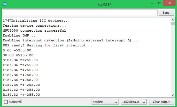
Here are the input and output values of the PID algorithm represented as input => output. If the bot achieves perfect balance, the output value will be 0. The current value from the MPU6050 sensor is the input value. The letter “F” indicates forward movement of the bot, while “R” indicates reverse movement.
In the beginning of PID tuning, I suggest keeping your Arduino cable connected to the robot for easy monitoring of input and output values, as well as for convenient correction and uploading of Kp, Ki, and Kd values. The video demonstrates the full functionality of the bot and provides guidance on adjusting your PID values.
If you encounter any issues with getting your self balancing robot to work, feel free to ask questions in the comments or on the forums for more technical support.
Code:
/*Arduino Self Balancing Robot
* Code by: B.Aswinth Raj
* Build on top of Lib: https://github.com/jrowberg/i2cdevlib/tree/master/Arduino/MPU6050
* Website: circuitdigest.com
*/
#include “I2Cdev.h”
#include <PID_v1.h> //From https://github.com/br3ttb/Arduino-PID-Library/blob/master/PID_v1.h
#include “MPU6050_6Axis_MotionApps20.h” //https://github.com/jrowberg/i2cdevlib/tree/master/Arduino/MPU6050
MPU6050 mpu;
// MPU control/status vars
bool dmpReady = false; // set true if DMP init was successful
uint8_t mpuIntStatus; // holds actual interrupt status byte from MPU
uint8_t devStatus; // return status after each device operation (0 = success, !0 = error)
uint16_t packetSize; // expected DMP packet size (default is 42 bytes)
uint16_t fifoCount; // count of all bytes currently in FIFO
uint8_t fifoBuffer[64]; // FIFO storage buffer
// orientation/motion vars
Quaternion q; // [w, x, y, z] quaternion container
VectorFloat gravity; // [x, y, z] gravity vector
float ypr[3]; // [yaw, pitch, roll] yaw/pitch/roll container and gravity vector
/*********Tune these 4 values for your BOT*********/
double setpoint= 176; //set the value when the bot is perpendicular to ground using serial monitor.
//Read the project documentation on circuitdigest.com to learn how to set these values
double Kp = 21; //Set this first
double Kd = 0.8; //Set this secound
double Ki = 140; //Finally set this
/******End of values setting*********/
double input, output;
PID pid(&input, &output, &setpoint, Kp, Ki, Kd, DIRECT);
volatile bool mpuInterrupt = false; // indicates whether MPU interrupt pin has gone high
void dmpDataReady()
{
mpuInterrupt = true;
}
void setup() {
Serial.begin(115200);
// initialize device
Serial.println(F(“Initializing I2C devices…”));
mpu.initialize();
// verify connection
Serial.println(F(“Testing device connections…”));
Serial.println(mpu.testConnection() ? F(“MPU6050 connection successful”) : F(“MPU6050 connection failed”));
// load and configure the DMP
devStatus = mpu.dmpInitialize();
// supply your own gyro offsets here, scaled for min sensitivity
mpu.setXGyroOffset(220);
mpu.setYGyroOffset(76);
mpu.setZGyroOffset(-85);
mpu.setZAccelOffset(1688);
// make sure it worked (returns 0 if so)
if (devStatus == 0)
{
// turn on the DMP, now that it’s ready
Serial.println(F(“Enabling DMP…”));
mpu.setDMPEnabled(true);
// enable Arduino interrupt detection
Serial.println(F(“Enabling interrupt detection (Arduino external interrupt 0)…”));
attachInterrupt(0, dmpDataReady, RISING);
mpuIntStatus = mpu.getIntStatus();
// set our DMP Ready flag so the main loop() function knows it’s okay to use it
Serial.println(F(“DMP ready! Waiting for first interrupt…”));
dmpReady = true;
// get expected DMP packet size for later comparison
packetSize = mpu.dmpGetFIFOPacketSize();
//setup PID
pid.SetMode(AUTOMATIC);
pid.SetSampleTime(10);
pid.SetOutputLimits(-255, 255);
}
else
{
// ERROR!
// 1 = initial memory load failed
// 2 = DMP configuration updates failed
// (if it’s going to break, usually the code will be 1)
Serial.print(F(“DMP Initialization failed (code “));
Serial.print(devStatus);
Serial.println(F(“)”));
}
//Initialise the Motor outpu pins
pinMode (6, OUTPUT);
pinMode (9, OUTPUT);
pinMode (10, OUTPUT);
pinMode (11, OUTPUT);
//By default turn off both the motors
analogWrite(6,LOW);
analogWrite(9,LOW);
analogWrite(10,LOW);
analogWrite(11,LOW);
}
void loop() {
// if programming failed, don’t try to do anything
if (!dmpReady) return;
// wait for MPU interrupt or extra packet(s) available
while (!mpuInterrupt && fifoCount < packetSize)
{
//no mpu data – performing PID calculations and output to motors
pid.Compute();
//Print the value of Input and Output on serial monitor to check how it is working.
Serial.print(input); Serial.print(” =>”); Serial.println(output);
if (input>150 && input<200){//If the Bot is falling
if (output>0) //Falling towards front
Forward(); //Rotate the wheels forward
else if (output<0) //Falling towards back
Reverse(); //Rotate the wheels backward
}
else //If Bot not falling
Stop(); //Hold the wheels still
}
// reset interrupt flag and get INT_STATUS byte
mpuInterrupt = false;
mpuIntStatus = mpu.getIntStatus();
// get current FIFO count
fifoCount = mpu.getFIFOCount();
// check for overflow (this should never happen unless our code is too inefficient)
if ((mpuIntStatus & 0x10) || fifoCount == 1024)
{
// reset so we can continue cleanly
mpu.resetFIFO();
Serial.println(F(“FIFO overflow!”));
// otherwise, check for DMP data ready interrupt (this should happen frequently)
}
else if (mpuIntStatus & 0x02)
{
// wait for correct available data length, should be a VERY short wait
while (fifoCount < packetSize) fifoCount = mpu.getFIFOCount();
// read a packet from FIFO
mpu.getFIFOBytes(fifoBuffer, packetSize);
// track FIFO count here in case there is > 1 packet available
// (this lets us immediately read more without waiting for an interrupt)
fifoCount -= packetSize;
mpu.dmpGetQuaternion(&q, fifoBuffer); //get value for q
mpu.dmpGetGravity(&gravity, &q); //get value for gravity
mpu.dmpGetYawPitchRoll(ypr, &q, &gravity); //get value for ypr
input = ypr[1] * 180/M_PI + 180;
}
}
void Forward() //Code to rotate the wheel forward
{
analogWrite(6,output);
analogWrite(9,0);
analogWrite(10,output);
analogWrite(11,0);
Serial.print(“F”); //Debugging information
}
void Reverse() //Code to rotate the wheel Backward
{
analogWrite(6,0);
analogWrite(9,output*-1);
analogWrite(10,0);
analogWrite(11,output*-1);
Serial.print(“R”);
}
void Stop() //Code to stop both the wheels
{
analogWrite(6,0);
analogWrite(9,0);
analogWrite(10,0);
analogWrite(11,0);
Serial.print(“S”);
}
Source: DIY Self Balancing Robot using Arduino
- What controller is used for the Self Balancing Robot?
The project uses an Arduino UNO as the controller. - Can I use DC gear motors instead of stepper motors?
Yes, the guide uses affordable yellow DC gear motors and states stepper motors are not required. - Which motor driver is used to control the DC motors?
The L298N motor driver module is used (L293D is mentioned as an alternative). - What sensor is recommended for measuring orientation?
The MPU6050 6-axis accelerometer and gyroscope is recommended. - What battery is used to power the robot?
A 7.4V Li-ion battery is used; the guide suggests a 7.4V Li-polymer battery is ideal. - How is the MPU6050 connected to Arduino?
MPU6050 uses I2C: Vcc to 5V, GND to Gnd, SCL to A5, SDA to A4, and INT to D2. - Which Arduino pins drive the motors?
Motors are connected to PWM pins D6, D9, D10, and D11 on the Arduino. - How does the robot determine when to move wheels forward or backward?
It reads yaw/pitch/roll from the MPU6050; if input deviates from setpoint, PID output directs Forward, Reverse, or Stop functions. - Do I need to tune PID values?
Yes, Kp, Ki, and Kd must be tuned for your specific bot; the guide provides example values and recommends monitoring via serial monitor. - Are 3D print files provided for the chassis?
Yes, STL and design files are available for download on Thingiverse according to the article.