Summary of DIY ESP32 Wifi Self Balancing Robot – B-Robot ESP32 Arduino Programing
This project shows how to build an ESP32-based self-balancing robot using a custom PCB shield and 3D-printed chassis parts. It covers ordering the PCB from PCBWAY, soldering SMD and through-hole components, attaching modules (ESP32, MPU6050, A4988 drivers), printing and assembling 3D parts, installing motors and electronics, and final assembly steps. The design is based on B-Robot EVO 2.0 and B-Robot ESP32.
Parts used in the ESP32 Balancing Robot:
- PCB ESP32 Balancing Robot Shield (PCBWAY project)
- ESP32 DEVKIT V1 board
- Stepper Motor Driver A4988 (2x)
- 3 axis Accelerometer and Gyro sensor MPU6050
- Stepper Motor Nema17 (2x)
- Servo Motor MG90S
- LED 3mm
- LED 3mm White Super Bright (2x)
- Active Buzzer
- V-Regulator 5V AMS1117 (SMD, 2x)
- Resistor 1K Ohm
- Capacitor 0.1uF
- Capacitor 100uF/16V
- Capacitor 220uF/16V (2x)
- Rocker Switch Dia. 20mm
- Rechargeable Battery Li-ion 18650 3.7V (2x)
- Battery Holder 2x 18650
- Micro USB Cable
- OTG Adapter
- Terminal Screw 2 pin 5mm
- Female Header 15 pin (2x)
- Female Header 8 pin (5x)
- Female Header 4 pin (2x)
- Male Header 2 pin
- Male Header 3 pin
- Jumper cap
- Set screw 5mm
- M3 set screw 10mm
- O-ring 3mm ID 82mm (2x)
- Set 3D Printed Parts (see list below)
This article is proudly sponsored by PCBWAY.
PCBWAY make high quality prototyping PCBs for people all over the world. Try it for your self and get 10 PCBs for just $5 at PCBWAY with very great quality, Thanks PCBWAY. The ESP32 Balancing Robot Shield that I developed in this project uses PCBWAY PCB services. In this instructable, I will show you how to build Self Balancing Robot use ESP32 Wifi. Let’s get started!
This self balancing robot is based on:
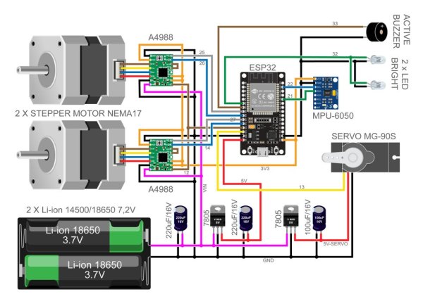
Step 1: Circuit Diagram
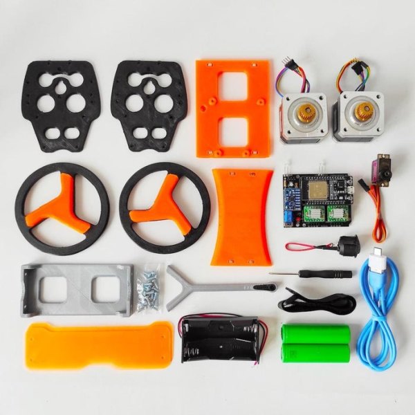
Step 2: Parts List
- 1 x PCB ESP32 Balancing Robot Shield (https://www.pcbway.com/project/shareproject/ESP32_Balancing_Robot_Shield.html)
- 1 x ESP32 DEVKIT V1 board
- 2 x Stepper Motor Driver A4988
- 1 x 3 axis Acc. and Gyro sensor MPU6050
- 2 x Stepper Motor Nema17
- 1 x Servo Motor MG90S
- 1 x LED 3mm
- 2 x LED 3mm White Super Bright
- 1 x Active BUzzer
- 2 x V-Regulator 5V AMS1117 (SMD)
- 1 x Resistor 1K Ohm
- 1 x Capacitor 0.1uF
- 1 x Capacitor 100uF/16V
- 2 x Capacitor 220uF/16V
- 1 x Rocker Switch Dia. 20mm
- 2 x Rechargeable Battery Li-ion 18650 3,7V
- 1 x Battery Holder 2x 18650
- 1 x Micro USB Cable
- 1 x OTG Adapter
- 1 x Terminal Screw 2 pin 5mm
- 2 x Female Header 15 pin
- 5 x Female Header 8 pin
- 2 x Female Header 4 pin
- 1 x Male Header 2 pin
- 1 x Male Header 3 pin
- 1 x Jumper cap
- 1 x Set screw 5mm
- 1 x Set M3 set screw 10mm
- 2 x O-ring 3mm ID 82mm
- 1 x Set 3D Printed Parts
Step 3: Order PCB on PCBWAY
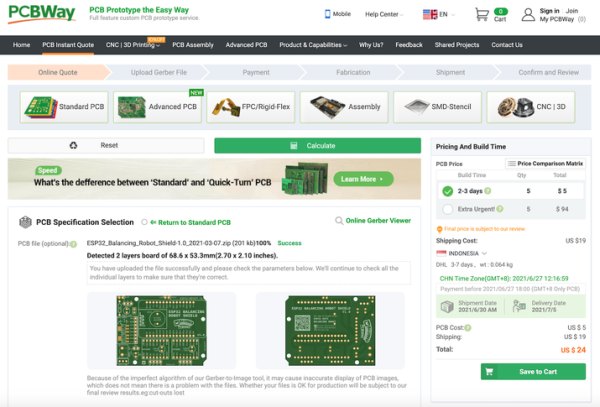
In order to create this project, you must purchase a prototype PCB from PCBWAY. Ordering is quite simple and for only $5, you will receive 10 Pcs of high-quality PCB.
Step to Order:
1. SignUp/Log in on pcbway.com
2. Open this PCB project link ESP32 Wifi Balancing Robot Shield
3. Click Add to cart.
4. Wait moment for PCB review, then Click Check Out.
Step 4: Solder SMD Component (AMS1117 5V)
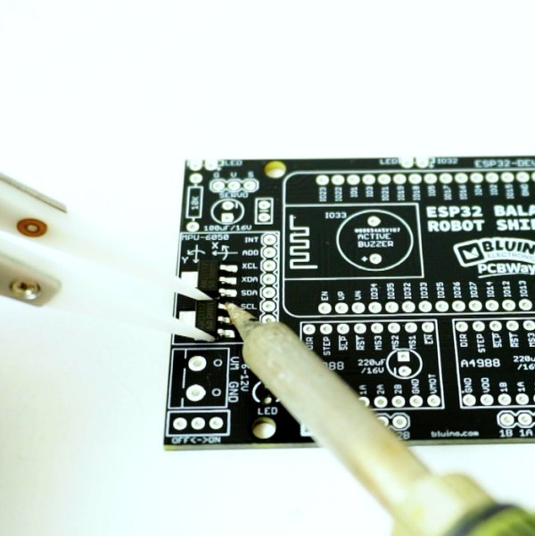
This project has two SMD component, it is not too difficult to solder because the size of the SMD component is quite large, so don’t worry.
You will need tweezers as a tool to hold the components when soldered.
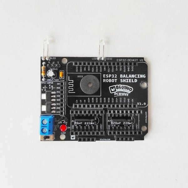
Step 5: Place the Components
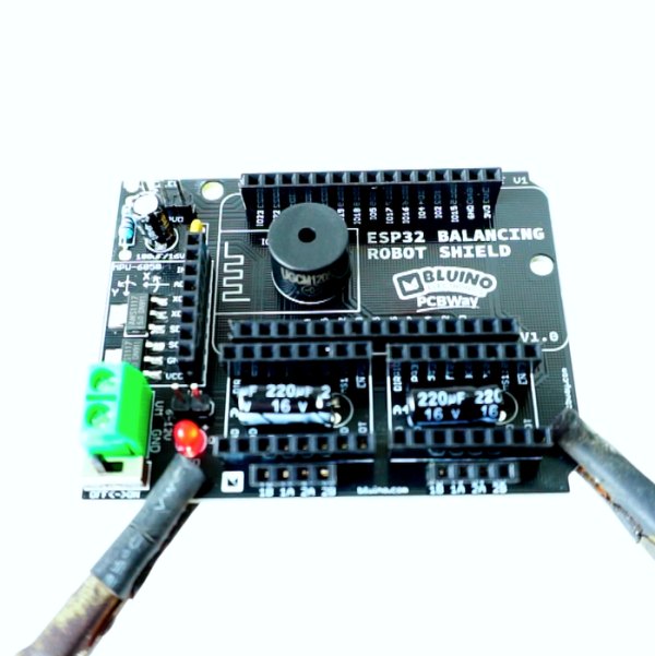
After finish solder SMD component, next attach other trough hole components on the PCB following the pictures and symbols on the PCB, for details you can follow step by step in the video.
Step 6: Soldering
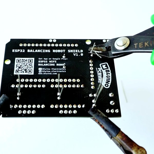
To attach every leg of the components to the PCB’s rear side, you can refer to the video for a detailed step-by-step guide.
After completing the soldering process, trim all the lengthy legs of the component wire.
Step 7: Attach Modules
Connect the ESP32 board, MPU6050, and two Driver Stepper Motor A4988 to the female header socket as demonstrated, pay attention to the pin names to avoid incorrect orientation.
Step 8: 3D Printed Parts
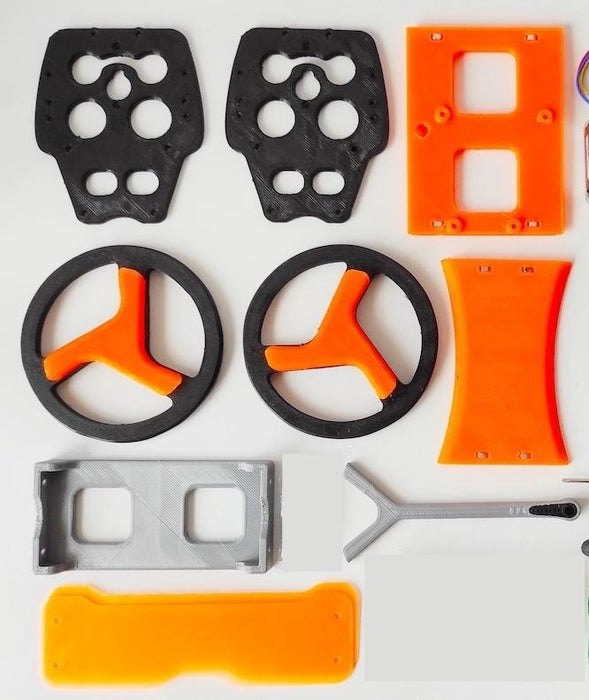
Print all of 3D parts Balancing robot, get design file from thingiverse.com/thing:2306541
List 3D Printed Parts:
- 2x Wheels
- 2x Hub Arm
- 2x Side Panel
- Top Shelf
- Motor Shelf
- Electronics Shelf
- 2x Bumpers
Step 9: Install 3D Parts
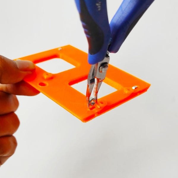
- Insert four M3 nuts into each hole on the edge of the Electronics Shelf (3d printed part).
- Install two Side Panel (3d printed part) on both sides then tie it with a machine screw.
Step 10: Install Stepper Motor
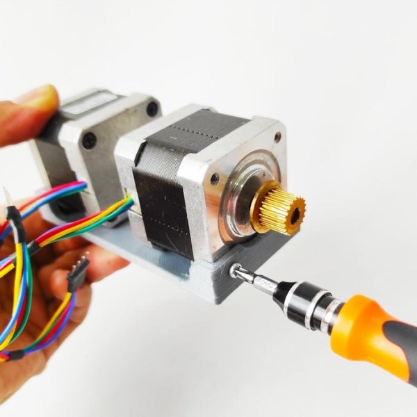
Attach two stepper motor Nema17 to the Motor Shelf (3d printed part) then tie it with a machine screw.
Step 11: Assembly Parts
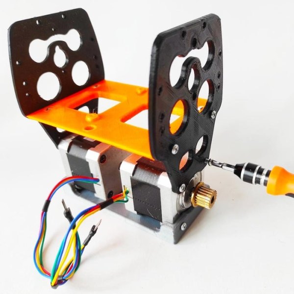
Attach Motor Shelf assy with Electronic Shelf Assy then tie it with a machine screw.
Step 12: Install Electronics Shield
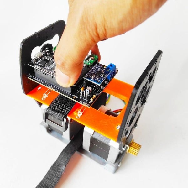
- Put the battery scrap under the electronic shield as shown.
- Attach ESP32 Balancing Robot Shield into Electronic Shelf then tie it with a wood screw.
Source: DIY ESP32 Wifi Self Balancing Robot – B-Robot ESP32 Arduino Programing
- Where can I get the PCB for this ESP32 balancing robot?
Order the PCB from PCBWAY via the ESP32 Wifi Balancing Robot Shield project link on pcbway.com. - What microcontroller board is used in this project?
The project uses an ESP32 DEVKIT V1 board. - Which IMU sensor is used for balancing?
The MPU6050 3 axis accelerometer and gyro sensor is used. - What motor drivers and motors are required?
The build uses two A4988 stepper motor drivers and two Nema17 stepper motors. - Are there any SMD components to solder on the PCB?
Yes, there are two SMD components: two AMS1117 5V regulators. - Where do I get the 3D part files for the chassis?
Download the 3D design files from thingiverse.com/thing:2306541 as stated in the article. - How many 18650 batteries are needed and how are they mounted?
The project uses two rechargeable Li-ion 18650 batteries mounted in a 2x18650 battery holder. - What additional connectors and headers are required?
The parts list includes various female headers (15-pin, 8-pin, 4-pin), male headers (2-pin, 3-pin), a 2-pin terminal screw, and a jumper cap. - Is assembly guidance provided for soldering and mounting?
Yes, the instructable describes soldering SMD and through-hole parts, inserting components into headers, and following the video for detailed steps. - Which project designs inspired this build?
The build is based on B-Robot EVO 2.0 by JJRobots and B-Robot ESP32.