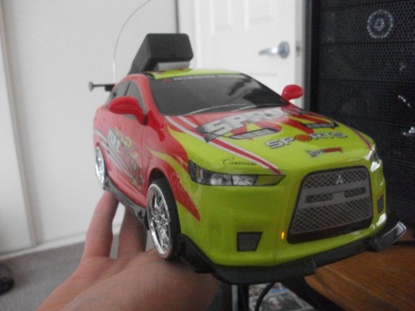
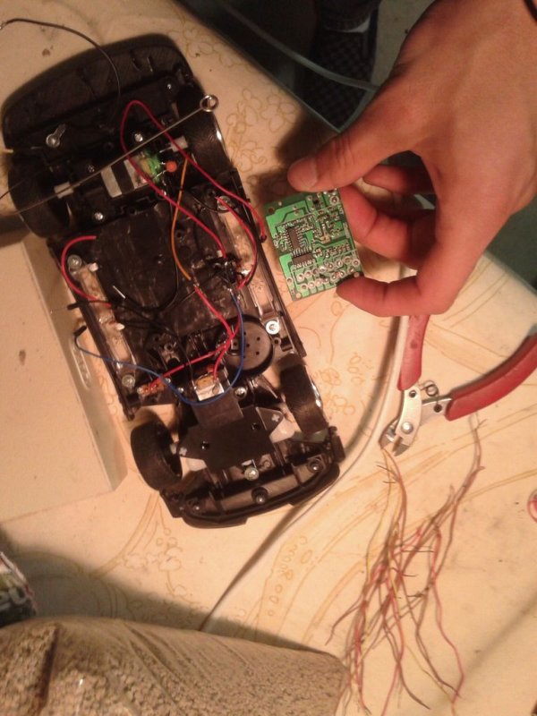
Required Parts: This project requires two Arduino boards which can be bought from http://www.adafruit.com/category/17
This project uses two Arduino Uno compatible boards.
An L293D or other Dual H-Bridge Motor Driver chip will be needed to drive the motors of the RC car. This can be found here: http://www.adafruit.com/products/807
Finally, this project requires the RF transmitter (https://www.sparkfun.com/products/retired/8945) and receiver (ttps://www.sparkfun.com/products/retired/8945) which will used for communication between the Arduinos.
A breadboard to prototype your circuit and a prototype board is also needed to solder everything together in the end. This can be bought from an electronics store like Jaycar Electronics.
Required Knowledge: A basic knowledge of electronics is required for this tutorial. If you have never worked with electronics take a look at this tutorial (at least up to lesson 4): http://www.ladyada.net/learn/arduino/
Knowing how to solder will also help with the final steps: https://learn.sparkfun.com/tutorials/how-to-solder…
This tutorial also assumes that you have a basic knowledge of the Arduino Uno and know how to program and upload a basic sketch. For the basics of Arduino, check out the Adafruit Arduino basics lessons at: http://learn.adafruit.com/lesson-0-getting-started/the-lessons.
A basic knowledge of Java is also assumed. You should know how to set up Java on your computer and create a basic Java program. This tutorial uses the Eclipse IDE. For the basics of programming Java and using Eclipse, check out this tutorial: http://eclipsetutorial.sourceforge.net/totalbeginner.html
Tutorial Structure: This tutorial will be split up into 3 parts:
- Sending Arduino
- Recieving Arduino
- Computer program
Step 1: Sending Arduino: Wiring and building.
Place the transmitter in the breadboard and wire the Ground and 5V pins to the corresponding Ground and 5V on the Ardunio. The data in pin should be connected to pin 12 on the Arduino. The antenna is optional but to gain more range, you can simply attach a long wire and leave it hanging.

Step 2: Sending Arduino: The Code.
This tutorial uses version 1.20 (download link: http://www.airspayce.com/mikem/arduino/) any version should be compatible.
At the top of the sketch put:
#include <VirtualWire.h> //include the required library
In the setup function put:
void setup()
{
  //Begin the serial connection
  Serial.begin(9600);
  while(!Serial); //Wait till serial connection is ready
  Serial.println("Serial ready"); //Debugging
  //Initialize the IO and ISR
  vw_setup(2000); // Bits per sec
}
This code simply initializes the serial connection and Virtual Wire.
The Loop function should look like this:
void loop()
{

  //If serial input is available
  if(Serial.available())
  {
    char input = Serial.read(); //Read input
    send(&input); //Send input via RF transmitter
  } else {
  }
}
This reads an input character and sends it to the send function.
Finally the send function should be created to look like this:
void send (char *message)
{
  vw_send((uint8_t *)message, strlen(message)); //Send the message
  vw_wait_tx(); // Wait until the whole message is gone
}
The send function takes a character and sends it using the Virtual Wire library.
This is all that’s required for the sending Arduino.
You can download the complete sketch from here: https://dl.dropboxusercontent.com/u/63127140/Simpl…
Step 3: Receiving Arduino: Wiring and building.
It requires both the RF receiver and the L293D chip.
The RF receiver:
The pins on the RF receiver labelled GND are ground. DATA OUT is where the received signal will be sent out. VDD is power for the chip and ANT is for the optional antenna.
-Wiring:
The RF receiver is connected separately from the L293D chip. The ground goes to one of the ground ports on the Arduino. The power in goes to the Arduino’s 5V output and the DATA OUT should be connected to pin 13 on the Arduino. The antenna can be left loose and later connected to the RC car’s antenna.
The L293D chip:
The pins on the L293D chip are shown on the diagram above. EN1 and EN2 are the motor enable pins. They act as a master on/off switch for each motor. IN1,IN2,IN3 and IN4 are the inputs that control the directions of each motor. If IN1 is powered and IN2 is not, the motor on OUT1 and OUT2 will turn one way. Likewise if the inputs are flipped, so too are the outputs and the motor will turn the other way. 0V is ground and +V is power for the chip. +Vmotor is used as a separate power source for the motors.
-Wiring:
The wiring for the l293D chip is not as complicated as it may look. The +V and the +Vmotor pins should be connected to and external power supply. In this project we will end up connecting these to the battery pack from the RC car. The IN1, IN2, IN3 and IN4 pins will be connected to pins 3,4,5 and 6 on the Arduino. The two motor enable pins are connected to pins 9 and 10 on the Arduino. The OUT1 and 2 pins go to one motor and OUT3 and 4 go to the other. It doesn’t matter which IN pins go to which pins on the Arduino or which OUT pins go to which leads on the motor as these will be defined in code.
Step 4: Receiving Arduino: The Code.
At the top of this sketch, also include the Virtual Wire library:
#include <VirtualWire.h> //Include required library
We will also define some constants that we will use to control our car:
#define FORWARD '8'
#define BACKWARD '5'
#define STOP '0'
#define LEFT '4'
#define RIGHT '6'
#define STRAIGHT '/'

#define TIMEOUT 500UL
Next comes the variables for the motor pins. The value of these variables will be whatever pin the wire is connected to on the Arduino. If you wired yours up differently make sure you update your code here:
int motor1Pin1 = 5;    // pin 2 on L293D is connected to this pin on the Arduino
int motor1Pin2 = 6;    // pin 7 on L293D                  "
int enablePin1 = 9;    // pin 1 on L293D                  "
int motor2Pin1 = 3;    // pin 10 on L293D                 "int motor2Pin2 = 4;    // pin 15 on L293D                 "
int enablePin2 = 10;    // pin 9 on L293D                 "
There are two variables to control the motor speeds:
int motor1Speed = 255; //max speed 255
int motor2Speed = 255;
The last variable is for the timeout counter:
unsigned long counter;
The setup function will set up the pins as required. It also set’s up Virtual Wire:
void setup()
{
    //Set pin modes
    pinMode(motor1Pin1, OUTPUT);
    pinMode(motor1Pin2, OUTPUT);
    pinMode(motor2Pin1, OUTPUT);
    pinMode(motor2Pin2, OUTPUT);
    pinMode(enablePin1, OUTPUT);
    pinMode(enablePin2, OUTPUT);

    //Set enablePin to the motors speed
    analogWrite(enablePin1, motor1Speed);
    analogWrite(enablePin2, motor2Speed);

    //Begin with motors off
    digitalWrite(motor1Pin1, LOW);
    digitalWrite(motor1Pin2, LOW);
    digitalWrite(motor2Pin1, LOW);
    digitalWrite(motor2Pin2, LOW);

    Serial.begin(9600);
    //Initialise the IO and ISR
    vw_set_ptt_inverted(true);    // Required for RX Link Module
    vw_setup(2000);                   // Bits per sec
    vw_set_rx_pin(13);           // We will be receiving on pin 23 (Mega) ie the RX pin from the module connects to this pin.
    vw_rx_start();                      // Start the receiver
}
The loop function will contain the following code:
void loop()
{
  //variables for Virtual Wire
  uint8_t buf[VW_MAX_MESSAGE_LEN];
  uint8_t buflen = VW_MAX_MESSAGE_LEN;

  //If we got a message from the serial port
  if (Serial.available())
  {
    //Reset the timeout counter
    counter = millis();
    //Drive the requested motor
    drive(Serial.read());

    //Otherwise check for a message from the reciever
  } else if (vw_get_message(buf, &buflen)) // check to see if anything has been received
    {
      //Reset timeout counter
      counter = millis();
      int i;
      Serial.println("recieved"); //Debug message
       // Message with a good checksum received.

      //For each command recieved
      for (i = 0; i < buflen; i++)
      {
          drive(buf[i]); //Drive requested motors
      }

      //If the counter is greater than the timeout (No signal recieved) then stop the car.
    } else if(millis()-counter >= TIMEOUT) {
      drive(STOP);
      drive(STRAIGHT);
    }
}
Finally we need to define the Drive() function:
void drive(int dir) {
  //Check which direction is requested (same for below)
  if (dir == FORWARD) {
     Serial.println("Forward");//Used for debugging

     //Set motor accordingly (same for below)
     digitalWrite(motor1Pin1, HIGH);
     digitalWrite(motor1Pin2, LOW);

  } else if (dir == BACKWARD) {
    Serial.println("Backward");
     digitalWrite(motor1Pin1, LOW);
     digitalWrite(motor1Pin2, HIGH);
  } else if (dir == STOP) {
     Serial.println("Stop");
    digitalWrite(motor1Pin1, LOW);
    digitalWrite(motor1Pin2, LOW);
  } else if(dir == STRAIGHT) {
    Serial.println("Straight");
    digitalWrite(motor2Pin1, LOW);
    digitalWrite(motor2Pin2, LOW);
  }else if (dir == LEFT) {
    Serial.println("Left");
    digitalWrite(motor2Pin1, LOW);
    digitalWrite(motor2Pin2, HIGH);
  }else if (dir == RIGHT) {
    Serial.println("Right");
    digitalWrite(motor2Pin1, HIGH);
    digitalWrite(motor2Pin2, LOW);
  }
}
For more detail: Computer controlled RC car with two Arduinos
