If you have read my first blog on the topic, than you already know what I’m experimenting with. Low price FM Radio, build with TDA7088 / YD 9088. It was obvious, that technology from the early 90-x is outdated. I mean, simple “search and hold” function of the radio.
- Scan function works only one way, up in the frequency.
- After switching power “on/off” you have to tune it again on your preferred radio wave.
- You have no means to know, what is the frequency it’s on.
- Occasionally you can’t “push” a tuner to the next station on the air, and have to send multiple commends.
The problem is that radio luck intellectuality, you can’t do much with RS trigger. Arduino, even it’s small and 8-bits only, just a monster on this matter, with CPU, ADC and EEPROM. Now it’s time to use them! Radio-2 able to automatically scan all radio station in the area, store them in non-volatile memory, and plus do a manual “tunning” – mostly for debugging purposes.
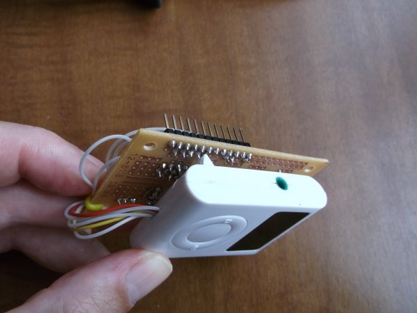
This version of the shield requires 4 wires (plus a cap, 4 resistors, and radio, of course). Two power lines, the same like in the first project, and other two connected to pin 1 of the IC and to variable capacitance diode. You also have to cut a trace, which connects Varicap and pin 16. Look at the schematic above.
Digital pin 9 of the arduino, internally driven by TIMER 1, is PWM-ed frequency control voltage to tune a heterodyne. FAST PWM mode, 10-bit is a compromise between PWM frequency and voltage resolution. We can’t get both, for example 16-bit PWM would drop a frequency down to 16 MHz / 65536 = 244 Hz, which is too low to be filtered by primitive RC filter, and plus not adequate to do a fast “sweep” or changes in tunning. The same time 8-bit PWM has low voltage resolution, and consequently creates too big “steps” in bandwidth. Measurements show, that radio has about 1 V / 20 MHz sensitivity of the VCO, which would imply to have a resolution at least: 1 V / 20 MHz / 200 kHz = 10 mV, where 200 kHz is a “spacing” in FM broadcasting schedule. 8 bit analogWrite has a resolution 5 V / 256 = .19.53 mV. Even resistors divider improves this value on 0.6 times (3 v / 256 = 11.72 mV), it’s still bigger than necessary minimum. With 10-bits I have 3V / 1024 = 2.93 mV. Using of external DAC isn’t an option for a few backs radio, but may be worse to try. PWM frequency with 10-bit equals to 16 kHz, which could be easily filtered out with 1-st order RC network.
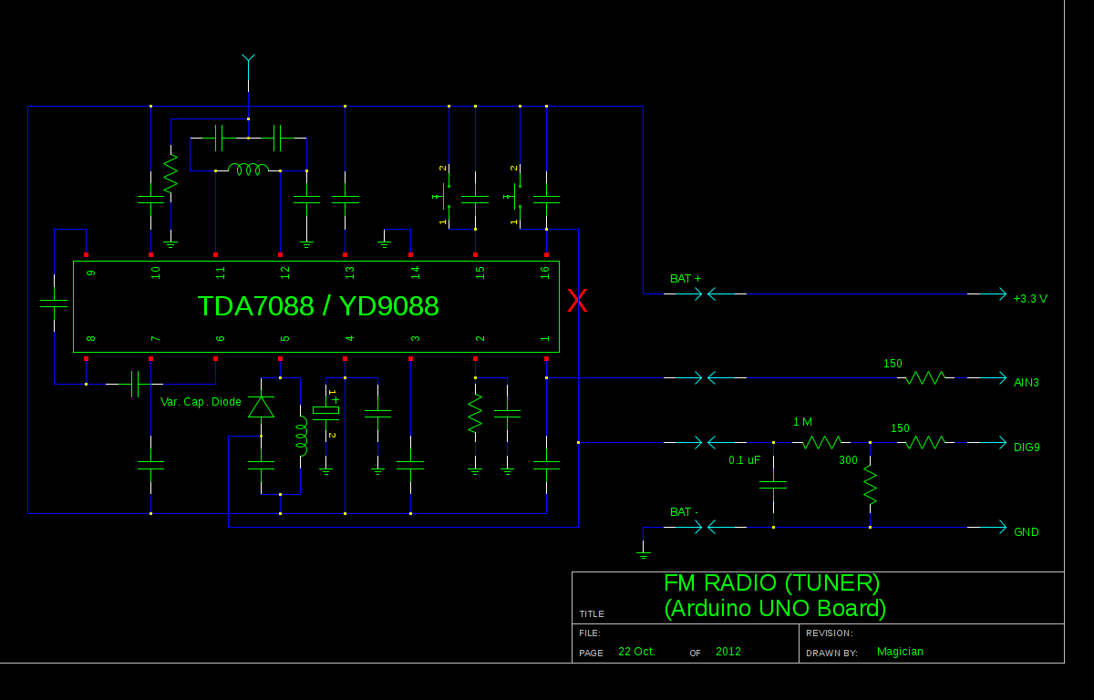
Analog pin 3 (AN3 ADC), reading the “signal strength” output line from the YD9088.
uint16_t read_tuner()  {   uint16_t temp = 0;
      for( uint8_t i = 0; i < 16; i++ ) {        ADCSRA |= (1<<ADSC);        while(!(ADCSRA & 0x10));        temp += ADC;       }    temp = 5 * temp / 16;    return temp;  }
As you can see, readings averaged over 16 values, which increases a resolution on two additional bits.
Search algorithm has a “window” of 5 samples, to be able to recognize a peaks in the incoming data.
For more detail: DIY Arduino FM Radio (Part 2)