Summary of How to Build a (Piezo) Knock Sensor Circuit
This article explains how to build a piezo knock sensor circuit using an Arduino. The knock sensor detects physical vibrations or knocks by producing a voltage signal. When a knock is detected above a set threshold, the Arduino lights an LED for 5 seconds. The piezo sensor connects to analog pin A0, with a 1MΩ resistor in parallel. The LED is connected to digital pin 13, which has a built-in resistor. The article includes a simple Arduino code to read sensor values and trigger the LED, providing a practical example of a sensor-activated circuit.
Parts used in the Piezo Knock Sensor Circuit:
- Piezo Knock Sensor
- 1MΩ Resistor
- LED
- Arduino Board
- USB Cable (Type A to Type B)
In this article, we go over how to build a piezo knock sensor circuit.
A knock sensor is a sensor which produces a voltage in response to some type of physical stress such as a knock or vibration. This is why it’s called a knock sensor; it detects knocks.
This sensor can be useful when you want a circuit to be able to respond to knocks that a user makes against them to turn on or off some load.
For example, in the circuit we will build in this project, an LED will light when a knock or vibration is detected.
But in actuality, a knock sensor is useful when we want a circuit to be sensitive and respond to any types of knocks.
Specificially, for this circuit, we will connect the knock sensor and an LED to the arduino microcontroller. When the sensor detects a knock, the microcontroller will then turn on an LED for 5 seconds, then shut it off.
 Components Needed for Accelerometer Circuit
- Piezo Knock Sensor
- 1MΩ Resistor
- LED
- Arduino Board
The piezo sensor can be obtained from Sparkfun at the following link: Sparkfun- Piezo Knock Sensor.
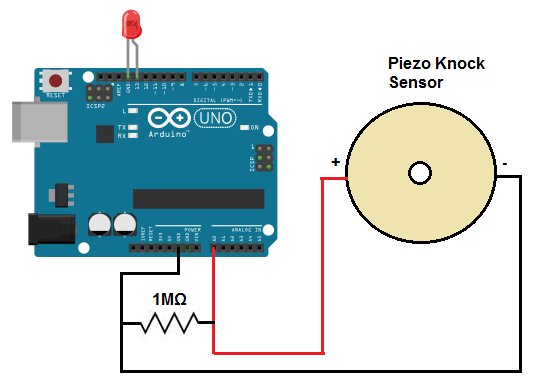
The piezo sensor has 2 leads, a positive lead and a negative lead. It is a polarized electronic component, so polarity must be observed in order for the sensor to work correctly in a circuit. The red lead is the positive lead and the black lead is the negative lead. The red lead connects to analog pin A0 on the arduino board and the black lead connects to the GND terminal on the arduino.
For this project, since we are running code from a computer and uploading it to the arduino board, you will need a laptop or desktop to write the code and a USB with one end having a type A connector and the other having a type B connector. The type A goes into the computer and type B goes into the arduino.
Piezo Knock Sensor Circuit Schematic
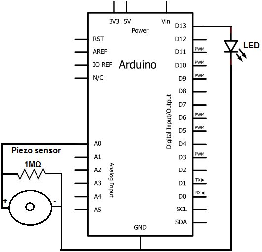
The piezo knock sensor circuit we will build is shown in the schematic below:
The positive lead of the knock sensor connects to analog pin A0 of the arduino board and the negative lead connects to ground (GND) of the arduino board.
A 1 megohm (1MΩ) resistor connects between both leads.
We connect the anode (positive lead) of the LED to digital pin 13 of the arduino. We connect the cathode (negative lead) of the LED to GND on the arduino board. Pin 13 has a built-in 220Ω resistor, so we do not need a current-limiting resistor when using this arduino pin.
Now that we have connected the circuit, we now need to create a program which will turn on the LED when a knock is detected.
Code
Code to turn LED on for 5 seconds when a knock or vibration is detected
const int sensorPin=0;
const int ledPin= 13;
const int threshold= 100;
void setup()
{
pinMode(ledPin, OUTPUT);
}
void loop()
{
int val= analogRead(sensorPin);
if (val >= threshold)
{
digitalWrite(ledPin, HIGH);
delay(5000);
digitalWrite(ledPin, LOW);
}
else
digitalWrite(ledPin, LOW);
}
Once we put this code in the arduino processing software and run the code, the LED will turn on for 5 seconds and then shut off.
Now we will explain each block of code.
The first block of code initializes all of the values we will need. Since the positive lead of the knock sensor connects to analog pin A0 of the arduino board, we initialize this pin, sensorPin, to 0. Since the LED’s anode connects to digital pin 13, we initialize this pin, ledPin, to 13. We then create a threshold of 100. Sbince there will always be some vibration in the external environment, we do not want the knock sensor to be triggered for very small vibrations.
 Only when there is a significant vibration or knock do we want the circuit to trigger. Therefore, the circuit will only be triggered when it is above a certain threshold. In our case, we make this threshold 100. You can experiment with this to suit your needs. By decreasing the value, the circuit will trigger for lower-sounding knocks. By increasing this value, louder knocks will have to made for the circuit to trigger.
In the second block of code, we make the LED an output pin.
In the third block of code, we create an integer called val which reads the value obtained from the knock sensor. If this value is above the threshold, we turn the LED HIGH or on for a period of 5 seconds (5000 μs) and then we shut it off. If the value is below this threshold, the LED remains off.
And this is the practical use and ability of a knock sensor circuit. We can create circuits which can respond to people’s knocks.
To see this circuit in action, watch the video below.
For more detail: How to Build a (Piezo) Knock Sensor Circuit