Summary of Simulating Logic Gates
This article describes an Arduino project that simulates logic gate behavior using LEDs and pushbuttons. By changing a single line of code, the circuit can demonstrate AND, OR, NOT, XOR, NAND, and NOR gates, effectively displaying their truth tables through light patterns based on input states.
Parts used in the Logic Gate Simulator:
- 2 x Yellow LEDs
- 1 x Red LED
- 3 x 330 Ohm Resistors
- 2 x 10 KOhm Resistors
- 2 x Pushbuttons
- Jumper Wires
Introduction
This project is a simple way of using the Arduino to simulate the behaviour of logic gates. Logic gates are explained on this page.
The project does not actually carry out the function of the logic gate, just turns a light on or off based on one or two inputs. Effectively showing the truth table for a given logic gate.
You Will Need
- 2 x LEDs Yellow
- 1 x LED Red
- 3 x 330 Ohm Resistors
- 2 x 10 KOhm Resistors
- 2 x Pushbuttons
- Jumper Wires
The yellow LEDs will be used to represent the input values, the red LED the output. The colour choice is up to you but it helps to make them different.
 Making The Circuit
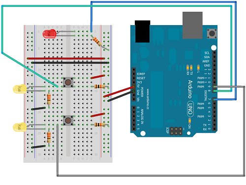
The following diagram shows how to connect the components,
The pushbuttons are connected with 10K resistors to GND. An LED is placed on the same row as the connections to the input pins (8 & 9). This gives us a push-to-make configuration for the pushbuttons. It also means that we don’t have to write any code to make the two input indicator LEDs light up. You can test the button connections early on. The Yellow LEDs in this diagram should light when the buttons are pressed and be off when not.
Programming The Arduino
int pinOut = 7;

int pinA = 8;

int pinB = 9;
void setup()
{
pinMode(pinOut, OUTPUT);
pinMode(pinA, INPUT);
pinMode(pinB, INPUT);
}
void loop()
{
boolean pinAState = digitalRead(pinA);
boolean pinBState = digitalRead(pinB);
boolean pinOutState;
// and
pinOutState =pinAState & pinBState;
digitalWrite(pinOut, pinOutState);
}
This is the basic code to demonstrate the behaviour of an AND gate. When uploaded, you should be able to see the output LED light when, and only when, both pushbuttons are pressed at the same time. Notice that boolean values are used here.
If you replace the line, pinOutState =pinAState & pinBState; with one of the following lines, you can simulate the other common logic gates. For the NOT gate, you only have a single input.
  //or

pinOutState = pinAState | pinBState;
// not
pinOutState = !pinAState;
// XOR
pinOutState = pinAState ^ pinBState;
//NAND
pinOutState = !(pinAState & pinBState);
//NOR
pinOutState = !(pinAState | pinBState);
 Challenge
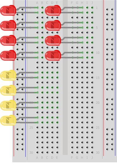
The challenge for this circuit is to come up with a much more interesting way to display the information. One way might be to do away with the pushbuttons for input and display a truth table. The following image shows how you might arrange the LEDs,
The red LEDs would be the inputs, the yellow the outputs. The left hand column of red LEDs would represent the state of input A, the right hand column input B. No resistors are shown here but you would need one per LED that can be on. Some of the red LEDs would never be on – these would simply be left unconnected. None of the red LEDs would need to be connected to Arduino pins either. Just connect the ones that represent a 1 to 5V on the anode with a resistor from the cathode to GND.
Each of the yellow LEDs needs a resistor and a connection to a different Arduino pin. If you can lay your hands on another breadboard, you could put the yellow output LEDs on that breadboard and line it up to make a nice table.
This would show the full truth table for a single logic gate. What would be nice would be to have some way to switch between logic functions using components. Some clever use of a pushbutton would allow you to move between logic functions.
Source: Simulating Logic Gates
- What is the purpose of this Arduino project?
The project simulates the behavior of logic gates by turning lights on or off based on one or two inputs to show the truth table. - How do you change the code to simulate an OR gate?
Replace the assignment line with pinOutState = pinAState | pinBState; - Can this circuit work without writing code for the input indicator LEDs?
Yes, placing an LED on the same row as the pushbutton connections allows them to light up when buttons are pressed without extra code. - Which pins are used for the inputs and output in the example code?
Pin 8 and Pin 9 are used for inputs A and B, while Pin 7 is used for the output. - How do you simulate a NOT gate in this project?
You use the line pinOutState = !pinAState; which requires only a single input. - What is suggested for displaying the full truth table more interestingly?
The challenge suggests using multiple red LEDs for inputs and yellow LEDs for outputs arranged in columns to display the full table. - How should the red LEDs be connected if not linked to Arduino pins?
Connect the ones representing a 1 to 5V on the anode with a resistor from the cathode to GND. - Is it possible to switch between different logic functions manually?
Yes, the article suggests using clever use of a pushbutton to move between logic functions.