Like many older people, my mom lives by herself. She likes her lifestyle but sometimes it gets a bit lonely. We talk on the phone a few times each week but it’s the in-between times where she could use a little emotional boost. A simple “I’m thinking of you” would be enough to make her smile but text messages just don’t cut it. This seemed like an interesting maker challenge with a feel-good finish line so I grabbed a few things I knew and learned a few things I didn’t.
Primary goals:
- Create a non-computer-interface way of communicating
- Make the UX very simple (she’s in her 80s, after all)
- Evoke the same visceral feeling as holding hands
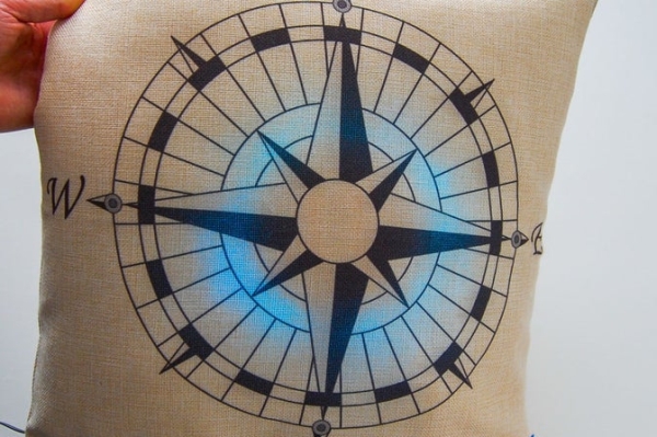
To achieve goal #1, I looked around her living room for normal, everyday objects that she already has. Turns out that throw pillows were pretty ubiquitous so I settled on this as the thing to connect.
That decision led to many questions… so many that I had to step back and settle on a few principles so that I’d actually deliver something.
Project Principles:
- Keep it simple
- Keep it modular
- During prototyping, emphasize speed over optimization
- Balance learning with doing
Results:
The end product made her (and me) very happy! She simply touches her pillow and mine sparkles, indicating a “call”. If I touch mine in response, both pillows will glow cyan which shows we’re connected. When I press again both pillows glow red, indicating that I’m “hanging up”. Obviously, we both need to be around our pillows at the same time but that’s the point; this is meant to be like I’m in the room with her.
We’ll use it in the evenings when she’s reading and I’m watching TV or on weekends when I’m running around and don’t have time to chat. My kids are always “calling” her and get a thrill when she “answers”. It’s kind of surprising what a small gesture can do for your spirits.
This Instructable:
This Instructable is involved and includes everything from soldering, to firmware engineering, to cloud computing to 3D printing. I’ve made all code and CAD files available but you’ll need your own AWS account (free for the first year and the costs associated with this project are tiny after that).
Also, you’ll need to make two of everything so keep that in mind before embarking!
Time required:
A weekend or two
Cost:
~$45 per electronic device. Add ~$10 per pillow if you don’t have any laying around.
Difficulty:
Moderate if you have some experience with the different skills involved. Advanced if you’re jumping in the deep end (mad props if you do!)
Step 1: Parts and Tools
You’ll need a bunch of stuff to build these. I’ve included links to Adafruit’s store where possible because they enable my making passions, have high-quality products and awesome learning materials (shout out to Becky Stern for her work there). Everything can be bought elsewhere but YMMV.
Electronic parts:
- 2 x Adafruit HUZZAH ESP32 Feather
- The link is to a board with pre-soldered headers. You can also buy them without headers if you want to save a couple bucks by soldering them yourself.
- 2 x Adafruit Perma-proto half-sized breadboard PCB
- I like this board as it has power and ground rails as well as numbered holes. These little time-saving features add up.
- 2 x 12mm tactile button switch
- 2 x 3 pin right angle JST PH jumper
- 2 x 2 pin right angle JST PH jumper
- Multicolored 22 AWG wire
- Heat shrink tubing
- One meter Adafruit NeoPixel RGB strip (to be cut into pieces roughly 12″ in length)
- I also tried their Mini Skinny NeoPixels which are smaller and denser. I actually prefer them for this project but they are more expensive and drain the battery faster. My code works with either so I’ll leave it to you to decide which you want.
- 2 x RAVPower 6700mAh USB power bank
- I didn’t want to mess around with LiPo batteries as they require proper handling and care. This power bank packs a long lifespan and is certified. It’s the most expensive part in this project.
Pillow parts:
- 2 x 18×18 throw pillow covers (Of course, you don’t have to get these particular designs. But I do recommend keeping the pillow cover art to a minimum so you can easily see the LEDs)
- 2 x 18×18 throw pillow inserts
- Batting
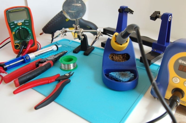
Tools:
Note – Tools can get expensive if you don’t already have them but consider it an investment in your making-future! I’ve found that a well-stocked workbench with quality stuff is worth the extra money. I’m listing the tools that I used but you can easily swap in your favorites.
Physical tools:
- Soldering iron – I use this Hakko station
- Lead-free solder
- Hot glue gun – I use a Stanley but any will do
- Super glue (you’ll only need a bit)
- Flush snips
- Wire strippers
- Solder sucker
- Third hand tool
- PCB clamp tool
- A micro USB cable
- The Feather has a micro USB connector; the other end needs to go into your computer so pick whatever works. Beware that some cheap USB cables lack the data wire and are only designed for charging; you won’t be able to see your Feather if you use one of these. If you run into this problem, change your cable. I used the cable that came with my RAVPower battery packs.
- Multimeter – I use the Extech EX330
- Testing your solder joints for continuity is optional but good practice. It can help you quickly diagnose problems that would cause you hours of headaches down the line.
- A computer with a hard drive (I have a Mac Powerbook. A Windows or Linux system should work too but I don’t know if Chromebooks will work)
- Scotch tape
- Foam mounting tape
- Scissors
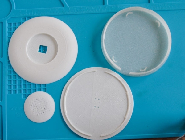
That blue thing in the photos is a silicone soldering pad. It saves my kitchen table from getting more burns but you don’t need it.
Software tools:
- Wifi (the ESP32 chip will talk to your WiFI router, which will then handle communication with AWS)
- IDE – I used VSCODE with the Arduino extension but you can just use the Arduino IDE if you already have it
- arduino-esp32
- USB to UART driver – This gives you the virtual port needed in order to flash the firmware
- Libraries (see the code for the full list)
- WiFiManager development branch (supports ESP32 boards). I love the out-of-the-box access point; this makes it super easy to configure WiFi at run-time instead of hardcoding networks and passwords into the firmware. The upshot is I can walk my mom through setup over the phone 🙂
- WiFiClientSecure – Because security is cool
- NeoPixelBus – Adafruit’s awesome NeoPixel library doesn’t work well on ESP32 boards. I won’t get into the guts but NeoPixelBus works great.
- Specific libraries are NeoPixelBrightnessBus and NeoPixelAnimator
- AceButton – An easy-to-use library that let’s me track different click types. My code monitors for single-click and long-pressed events.
- Arduino-MQTT – MQTT is a very lightweight protocol over TCP. This is one of many libraries out there
- ArduinoJSON – JSON is the format of choice for MQTT messages
- AWS IoT Core
- AWS is but one of many options for IoT services. Arguably, there are simpler ones I could have used for this project but I like all the extras AWS brings to the table. It’s nice having logs and events built in and you can easily pipe things to alarms that send you a text message (this came in really handy when I was troubleshooting seemingly random disconnects).
Step 2: Soldering the Protoboard
(If you’re new to soldering, check out this tutorial first)
Lay out everything you need within arms’ reach so you don’t have to get up once work begins.
Prepping the wires:
- Cut eight 5 cm wires: two red, two black, two white and two yellow. Strip the ends. Test the length of the red and black wires by placing them on the protobards from rail to rail. You’ll want them to be flush to the board for that nice, clean look (if it matters to you).
- Cut ten 2 cm wires: four red, six black. Strip the ends
- Tin the wires
Solder ESP32 Feather to protoboard:
- Place the protoboard into your PCB clamp
- Insert the Feather so that the RST header pin goes into B5 of the protoboard (Triple check this step because everything else depends on it!)
- Stick a piece of tape on there so the Feather doesn’t fall out when you flip it over
- Flip it and start soldering – I like to use a bevel tip and 800F iron
- Solder pins at opposite corners so the board is held in place
- Solder the rest of the pins – the order doesn’t matter
- Inspect all joints closely! You don’t want any shorts or bum connections. I keep a magnifying glass on hand to do quick checks
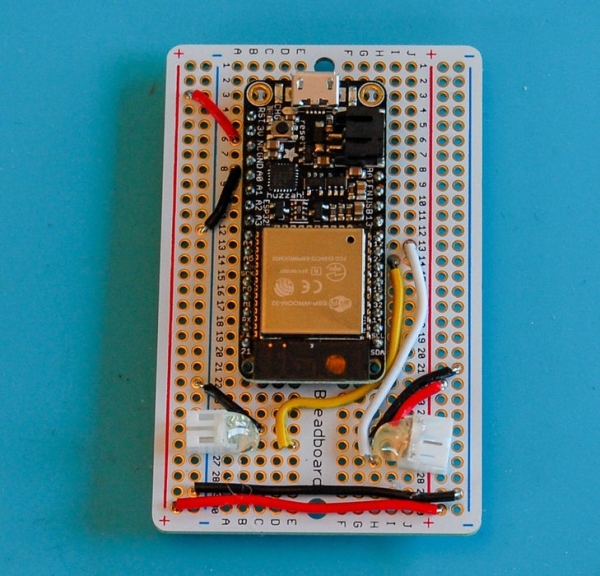
Solder wires and connectors to protoboard. Trim wires as needed. In these steps, hole numbers should be followed exactly when I include a row letter and used as guidelines when attaching to power and ground rails):
- Solder a red 5 cm wire from one power rail to the other across the board
- Solder a black 5 cm wire from one ground rail to the other across the board
- Solder a 2 cm red wire from A6 (Feather 3V pin) to power rail 4
- Solder a 2 cm black wire from A8 (Feather GND pin) to ground rail 11
- Solder a 2 cm black wire from C25 to ground rail 22 or 21
- Solder a 5 cm yellow wire from I14 (Feather pin 27) to E26
- Solder a 2 cm red wire from I25 to power rail 23 or 22
- Solder a 2 cm black wire from H26 to ground rail 22 or 21
- Solder a 5 cm white wire from J13 (Feather pin 12) to H27
- Place the 2 pin JST plug in A25 and A26 (position plug so it faces outward). Add tape to secure, flip over and solder
- Solder the 3 pin JST plug to J27, J26, J25 (position plug so it faces outward). Add tape to secure, flip over and solder
At this point you can turn your multimeter to the continuity setting and test all your joints (there are plenty of YouTube videos that will teach you how to do this).
Now take your flush snips and carefully snip off all the legs on the bottom of the board. Don’t worry about getting it absolutely flat, just clean it up. In fact, if you clip to close you risk upsetting a joint. Tip: Put a bag around the board when snipping so the debris doesn’t go flying everywhere.
Put a small piece of tape on the Feather board with an identifier, e.g. 1, 2, etc . This will save you time later when you’re stuck thinking “now which board is this?”
Did you get here? Awesome! Now do it again because you’re building two :-p
Step 3: Soldering NeoPixels
NeoPixels:
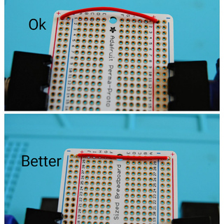
I went through a few versions to figure out the best way to position the NeoPixels. Initially, they were pointing straight up but I didn’t like the look. Eventually I hit upon arranging them in a circle, facing outward. This gave me a large illumination space and smoothed out the look of the animations.
The NeoPixels will wrap around the outside of the enclosure which has a diameter of 105 mm; this means the circumference is 105 * Pi, or roughly 330 mm. If you’re using the 30 LED per meter role, then cut after 10 pixels. Be sure you leave the copper pads on at the start but you can trim them off the end.
Note that the enclosure has a 15mm opening for wires & the USB plug to pass through so you don’t want to cover that with the strip. If you’re using the Minny Skinny NeoPixels with 60 LEDs per meter, you’ll cut after the 19th LED. Now prep and solder.
- Remove the silicone sleeve from NeoPixels. Lay strip flat
- Add a daub of solder to each of the copper pads on the input side of the NeoPixels (look for the arrow to make sure you’re soldering the correct end)
- Tin the wires of the 3 PIN JST wire
- Line up the wires with the associated pads. Red for power, black for ground and yellow for data.
- For each of the wires, hold the one you want to solder next to its pad, place the soldering tip on the pad to liquify the solder you put there in Step 3, then gently lay the wire on top. The wire should submerge into the solder and when you remove your iron, you’ll have a sweet junction. Do this quickly so as not to burn off the pads
- Inspect the joints Are they secure? Are they separate? Consider a quick continuity test with your multimeter
- Cut a 2 cm piece of heat shrink tubing and slide it over the wires and newly soldered connection.
- Hold a lighter under the tube for a couple of seconds and watch it shrink (be careful!)
- Add a small blob of hot glue to the wire end of the heat shrink for extra support
Step 4: Printing the Enclosure
Electronics need a housing! There are some great tools and resources out there for CAD/CAM design – Fusion 360 is free for hobbyists and you can find plenty of good on-line courses to teach you the basics. I really liked Designing for 3D Printing with Fusion 360 by Vladimir Mariano. Udemy runs sales and you can get the course for as cheap as $12.
Anyway, for this Instructable, I’ve made the STL files available so you don’t have to do any design work. But you will need access to a 3D printer and printing software like Simplify3D. I went down to my local maker space (props to Artisan’s Asylum) and used Flashforge printers with PLA filament.
There are four separate files:
- Case_body.stl – This is where you’ll put the protoboard and NeoPixels
- lid.stl – A thin section with ridges to snap onto the Case_body and four tiny holes for the legs of the electronic button
- Button_lid.stl – A half dome that sits on top of the lid and has an opening for the top of the electronic button
- button.stl – A 51mm wafer that we’ll glue to the top of the electronic button to increase its surface area
I used the same settings for each: 30% infill, no scaffolds, a thin brim, 60C for bed and 200C for extruder. Because the enclosure won’t be visible I didn’t care about color or aesthetics – I just wanted it to print quickly. If you look closely at the finished product you can see the ugly filament matrix; if this bothers you, increase the infill percentage.
Printing steps:
- Open individual files in your slicer software
- Position on bed, making sure the flat side is on the bottom
- Edit settings as described above
- Save as g code file
- Start print
Hang around for the first layer to ensure a good start to the print. Since the enclosure has a somewhat wide diameter, errors pop up early. Once it looks good, go get a beer. All told, it took me nearly 7 hours to print the four parts so print parts simultaneously if you have a large enough bed size. Remember, you’ll need two copies of each part!
Step 5: Electronic and Enclosure Assembly
It’s time to put it all together. For this you’ll need your hot glue gun and your soldering iron so get them hot and follow these steps:
- Lid assembly
- Run a spiral of glue around the lid’s flat side
- Line up the button lid’s flat side with the lid, making sure the four tiny holes for the button legs are all visible. Press together and hold for around 20 seconds for the glue to dry a bit
- Button assembly
- Working from the top of the button lid, insert the legs of your 12mm button switch into the tiny holes. Use some tape to prevent the button from dislodging and turn over
- Pick two legs that are diagonally apart from each other and tin them with solder – be careful not to touch the plastic or it will melt and gunk up your tip!
- Tin the ends of your 2 pin JST wire
- Carefully solder wires to the legs (it doesn’t matter which goes to which)
- After inspecting the joints, add a couple blobs of hot glue to secure it in place. Turn over and remove the tape.
- Add a drop of super glue to the very top of the button switch, being careful that none drips down the side. Press the flat side of your 3D printed button onto the glue and hold for a couple seconds. Click a few times, you deserve it!
- Note that the button attachment doesn’t have to be super durable because there won’t be much room for it to move once in the pillow
- Attach the NeoPixels
- Grab the case and quickly run a thin line of glue around the edge, towards the bottom
- With the LEDs facing out, bend the strip around the left side of the case opening (the first LED should be within a centimeter of the opening) and wrap in a clockwise direction around the case. Gently press into the glue – be careful not to touch the glue with your fingers! Align as needed so that the distance between the first and last LED is about the same as the connected LEDs on the strip. Make sure the strip doesn’t block the opening!
- Attach the JST plugs for the button and NeoPixels to their connections on the protoboard
- Place a couple blobs of hot glue in the center of the case and stick on the protoboard – it should be nested in between the ridges with the cable sticking out of the opening
- Grab the lid, line up an opening on the side of the lid with the case opening and press down to snap together. If you open it in the future, be careful not to pull off the button wires!
Step 6: Configuring AWS

Web-connected IoT devices need two things: a gateway and a broker. For this project, your home WiFi router is the gateway to the internet and AWS is the broker. The job of a broker is to route messages to and from recipients. The messages are commonly in JSON format and are transmitted using a protocol called MQTT. For an introduction to IoT see How AWS IoT Works.
You can create “things” on AWS in several ways and we’ll do it using the console (personally, I like to do this type of work as code but I don’t want to clutter this Instructable with environment settings, etc). If you don’t already have an AWS account, take 10 mins to go set it up (it’s free for the first year) and also set up a billing alarm for safety. For this section, I’m going to assume you know a bit about AWS, IAM and policies but I’ve tried to make the steps concise enough that you can get to a successful end result even if this is new to you.
Ok, see that physical Adafruit Feather board on the table? It only one part of your thing. Since it’s in the real world, we need something to identify it in the virtual world so that we can establish secure communication and this is called a certificate. Certificates can’t do anything unless they are associated with a real-world thing and have permissions. The permissions are recorded in something called a policy.
Create the thing and certificate:
- Log onto AWS management console
- Navigate to Services -> AWS IoT Core
- Click Manage
- Click the Create button
- Create a single thing
- Add the Name, feather_esp32_1 (you can name it whatever you want). Leave everything else as default and click Next
- Click Create certificate for the first option, titled, One-click certification creation
- Create a folder on your computer named after your thing and download the three files into it
- Click the link to download a root CA for AWS IoT
- The link with take you to another page where you’ll choose Amazon Root CA. Copy the contents and paste into a new file on your computer named AmazonRootCA1.pem
- Click the “Activate” button for the certificate
- Do it again for your second thing (give it a slightly different name)
Create the policy:
- Navigate back to AWS IoT Core
- Click Secure -> Things
- Click Policies
- Click Create
- Name it pillow-policy
- Under Add statements, click Advanced mode
- Paste the contents of pillow-policy.json (found at the bottom of this section) into the box, overwriting everything else in there
- Click Create
A word on policies: The best policies are the most explicit. The one I’m providing is wide open and therefore not secure. I didn’t restrict it because that would add more variables to the mix with an already complex project. Once you get everything working I highly recommend learning a bit about how to better restrict your IoT policies.
Attach policy to certificates:
- Navigate back to AWS IoT Core
- Click Secure -> Certificates
- For each certificate you created, click the little “…” icon on the right a select Attach Policy
- Check pillow-policy and click Attach
Ok, to summarize, we’ve created two things, two certificates and one policy. The certificates are associated with the things and the policy is attached to the certificates. Golden. Onward.
Step 7: Flashing Firmware
This is the step where we upload the firmware to the boards. You’re almost finished!
Prerequisites:
Make sure you have your environment configured properly:
- Arduino IDE installed
- If using VSCode, install the Arduino extention
- Install arduino-esp32
- Libraries listed in the Parts and Tools section downloaded and available in a place Arduino can see them
- See the Arduino Libraries page for more info
- USBtoUART driver installed
Code:
- Download the file from this section and unzip
- Change the name of Config.h.template to Config.h
- Change the name of certificates.h.template to certificates.h
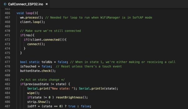
- Open CallConnect_ESP32.ino in your IDE
- Modify the configuration files as follows:
Config.h
- Replace “|device id|” with the name you gave your thing in the AWS step (keep the double quotes)
- Replace “|access point password|” with a password of your choice. This password will be required when connecting to your Feather’s access point during the WiFi configuration step (keep the double quotes)
- Replace |num pixels| with the number of LEDs on your NeoPixel strip (no double quotes)
- Replace “|endpoint|” with your AWS IoT endpoint (keep the double quotes). You’ll need to get this from AWS:
- AWS Management Console
- Services -> IoT Core
- Settings
- Copy the value shown in custom endpoint
- Replace “|mqtt topic|” with any name you choose; “pillow”, for example
certificates.h
- Open the AmazonRootCA1.pem file that you downloaded earlier in a text editor. Select all and copy the contents onto your clipboard and switch back to certificates.h
- Replace “|root|” with the contents of your clipboard. Then add line break characters, following the directions in the file
- See certificates.h.example for syntax reference
- Repeat with your private key file and certificate file you downloaded earlier (note that the public key file you downloaded doesn’t go into certificates.h)
- Double & triple check the formatting of the file. If anything is wrong, your thing won’t be able to connect to AWS
Flashing the code:
- Grab your first device and plug the USB cable into your computer
- Open CallConnect_ESP32.ino in your Arduino IDE
- Select your board
- Tools -> Board -> Adafruit ESP32 Feather
- Note you’ll probably see this board under the ESP32 Arduino Boards section and not under the Adafruit Boards section (confusing, I know)
- Tools -> Board -> Adafruit ESP32 Feather
- Select the port
- Tools -> Port -> /dev/cu.SLAB_USBto_UART
- If you don’t see this port, make sure you installed it correctly from the link above
- If installed correctly, try a different USB cable
- If still no, restart your IDE
- Tools -> Port -> /dev/cu.SLAB_USBto_UART
- Click “Verify” to compile the code and make sure you don’t get any errors. If you do get some, review the messages to find out why. Common causes are missing libraries or not having Config.h and/or certificates.h in the right directory.
- Click Upload and monitor the progress. Once 100% uploaded, open the Serial Monitor in your IDE and you should see the following output
If it worked, you’ll see this in the Serial Monitor
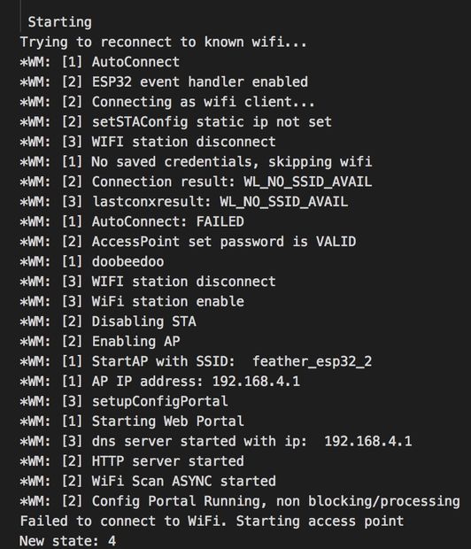
Here you can see the network name is set to “feather_esp32_2” and the access point password is “doobeedoo”.
Now repeat for the second board.
Step 8: Connecting to Your WiFi
(Note that you can complete this step with your device plugged in to either your computer or the battery. The settings will persist when power is removed, assuming you power it back up next to the same WiFi)
If the NeoPixels are connected correctly, you’ll see an animation of yellow lights spinning around (if not, check the JST plug and solder connections).
A word about Access Points
What’s happening here is that the board wakes up and looks in memory for saved network credentials. If it can’t find any, or if it can but the network isn’t available, it will start its own web server called an “access point”. This access points exists simply to give you a web page where you can tell the chip what network you want it to connect to, e.g. your home WiFi’s 2.4Ghz network (note that ESP32 won’t work on 5Ghz networks).
With your iOS or Android device, or your computer, check the available WiFi networks and you’ll see one named after your thing.
Source: Web-connected Glow Pillows