
Summary of Using FM RC Controllers using an Arduino
This article details a project where an old RC transmitter and receiver are used to control LEDs via an Arduino. The author identified the receiver's standard PWM signal, connected it to the Arduino using specific pins for power, ground, and signal, and wrote code to map pulse widths to LED brightness. The project was extended to control an RGB LED, demonstrating how remote joysticks can interact with microcontrollers.
Parts used in the RC Transmitter Controlled LED Project:
- RC Transmitter
- RC Receiver
- Arduino
- LED
- RGB LED
- Extension Cable
I recently dug up my old RC transmitter and receiver and thought “How can i control my arduino with this?” so i powered on my scope to see what was going on at the receiver. Sure enough, it was sending out the standard PWM signal that servos use. Now I just needed something to control. What’s easy and fun to control? LED’s of course.
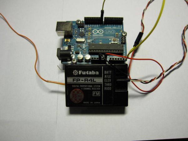
Step 1: The Receiver
To begin with i had to figure out what pin on the receiver was the signal pin for the servo. I found an extension cable, there i could clearly see what pin it was.
Step 2: Connecting it all
Now that i knew what pins were what i connected them to the arduino as follows:
I connected the signal to pin 8
and the led was connected to pin 11 because it has PWM capabilities.
I also connected the receiver ground to the arduinos ground and the 5v out from the receiver to the Vin on the arduino
Step 3: The Code

Now i started coding,
I used the pulseIn() function to read the pulses from the receiver and send them to the serial monitor, when i had those values i told the arduino to map those to the PWM values (0-255) and send them to the serial monitor again.
Now when i moved the joystick on the remote i saw the values change.
Now the last part of the code sends those PWM values to the led and fades it accordingly.
I was happy when i got this working but i needed a bit more challenge, i wanted it to control an RGB LED.
RGB LED
For more detail: Using FM RC Controllers using an Arduino
- How did the author identify the signal pin on the receiver?
The author found an extension cable where the signal pin for the servo was clearly visible. - What function was used to read pulses from the receiver?
The pulseIn() function was used to read the pulses from the receiver. - Which Arduino pin was used for the receiver signal?
The signal was connected to pin 8 on the Arduino. - Why was pin 11 chosen for the LED connection?
Pin 11 was selected because it has PWM capabilities. - How were the received values converted for the LED?
The Arduino mapped the pulse values to PWM values ranging from 0 to 255. - What type of signal does the RC receiver send out?
The receiver sends out the standard PWM signal that servos use. - Can this setup control an RGB LED?
Yes, the project was extended to control an RGB LED by sending the mapped PWM values. - What happens when the joystick is moved?
When the joystick is moved, the serial monitor shows changing values which fade the LED accordingly.
