This is a project in attempting to improve it predecessor “Freeform Arduino” by putting it in an enclosure and having it serve the similar purposes as “Palm Arduino Kit” and “Palm Arduino II” which I can carry it in my pocket and be available to use, and to connect to easy available power source specifically USB port.
.
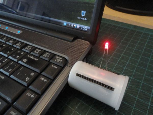
I designed this “USB Freeform Arduino” with USB connector to be enclosed inside a 35mm film canister.
The biggest challenge is how I couid fasten the “none PCB Arduino” to it own enclosure, in this case cylinder shape canister?
The answer was not an easy one. But the solution I found was an easy thing to do, and it was an excellent solution that we quite familiar with.
“How about glue it in!”, I said to myself.
Step 1: Parts and Tools
All the parts are about the same as used in it predecessor, “Freeform Arduino” except that I used film canister instead of the antistatic tube, with an addition USB type A connector.
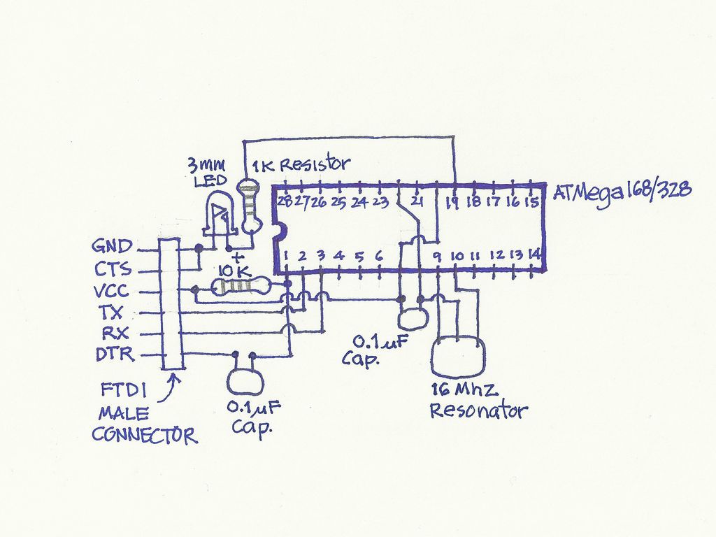
Schematic shown below is comprised of the minimum components and could be used FTDI cable to upload the sketch.
On the actual USB Freeform Arduino did not included the 1K resistor and 3mm LED that connected to pin D13 as in the schematic.
Parts
These are the minimum components to get Arduino up and running.
(1x) ATmega168/328 preloaded with Arduino Bootloader
(1x) 16 Mhz Resonator
(2x) 0.1uF Ceramic Capacitors
(1x) 3mm red LED (Only needed for testing purpose only)
(1x) 1K Resistor
(1x) 10K Resistor
(1x) 6-pin Male Header (as the connector to FTDI cable to upload the sketch)
(2x) 1×14 Female Receptacle
Additional Materials:
Hookup Wire
35mm Film Canister
USB Standard type A cable (Male Connector)
Tools
Solder iron and Solder station
Diagonal Cutter
Pliers
X-Acto Knife
Wire Stripper
SolderSucker
Miniature Files
Hand Drill
Micro drill bit for Hand drill
Masking tape
Super Glue
Step 2: Make Freeform Arduino
To make Freeform Arduino,
I started out by connecting the VCC and AVCC pins, pin number 7 (the actual pin number, not the Arduino’s digital pin 7) and pin number 20 of ATmega168/328, together. And I also joined GND pins, pin number 8 and pin number 22 of ATmega168/328 together.
(See pins map here)
14-pin Female Receptacles
I soldered 14-pin receptacles to both sides of ATmega168/328 (with boot loader installed.) I set the angle of the 14-pin receptacles to lean a little bit outward to match the curvature of the canister cylinder shape.
0.1uF Capacitor
The capacitor does not have polarity. So I soldered left pin of the capacitor to ATmega168/328 pin number 7. And soldered the right pin of capacitor to ATmega168/328 pin number 8.
16kHz Resonator
The resonator has three pins, left and right are to be connected to XTAL1 and XTAL2 on ATmega168/328 (pin number 9 and 10). So, I soldered the right most pin of the resonator to pin number 10 (XTAL2), and used hookup wire to connect the left pin of resonator to pin number 9 of ATmega168/328. And used short hookup wire to join ground pin of resonator (middle pin) to ATmega168/328 pin number 8 (Ground).
FTDI connector
I soldered six hookup wires to 6-pin Male header in this order (pointing the header out toward my right hand side).
And I soldered the hookup wires to ATmega168/328 as shown below.
ATmega168/328 Hookup wire FTDI pins
Ground Pin (8 or 22) Black GND
– – CTS (I connected this pin to GND pin above)
VCC Pin (7 or 20) Red VCC
RX Pin (2) White TX (out)
TX Pin (3) Green RX (in)
Reset Pin(1) Green DTR/RTS (I soldered 0.1uF ceramic capacitorbetween male header and hookup wire.)
After all the wires connected, I used SuperGlue to glue the FTDI header to the end of 14-pin receptacles over pin number 1 and 28 of ATmega168/328.
10K Resistor
I soldered 10K resistor in between VCC pin (pin number 7) and Reset pin (pin number 0) of ATmega168/328.
Note: For the details of how to make “Freeform Arduino” see the making steps of “Palm Arduino Kit”, since it have the same schematics and it did not use PCB. There is no different in how to built steps between the First and this one, except Freeform Arduino does not have pin D13 LED and resistor.
Step 2: Straighten the pins (NOTE: Do not straighten the “USB Freeform Arduino”)
Step 3: Added Power and Ground
Step 4: Bring out the pins (Note: You could bring out only digitals and analogs only and not omit the XTAL1, XTAL2, and GND pins – 8, 9, and 10 in this “USB Freeform Arduino” just like I did in “Palm Arduino II)
Now, we have Freeform Arduino ready for the next steps.
(1x) ATmega168/328 preloaded with Arduino Bootloader
(1x) 16 Mhz Resonator
(2x) 0.1uF Ceramic Capacitors
(1x) 3mm red LED (Only needed for testing purpose only)
(1x) 1K Resistor
(1x) 10K Resistor
(1x) 6-pin Male Header (as the connector to FTDI cable to upload the sketch)
(2x) 1×14 Female Receptacle
For more detail: USB Freeform using an Arduino