The Oshman Engineering Design Kitchen (OEDK) is the largest makerspace at Rice University, providing a space for all students to design and prototype solutions to real-world challenges. To serve this purpose, the OEDK houses a number of power tools and large machinery that produce loud, potentially unsafe noises. While the OEDK has successfully established a culture of safety around eye protection and gloves, it has been unable to establish the same culture of safety around hearing protection, due to the fact that users are unsure of when hearing protection is required.
Our team, Ring the Decibels, aims to solve this problem by designing, building, and implementing an alert system that advises OEDK users to wear appropriate hearing protection at unsafe sound levels.
Step 1: Overview
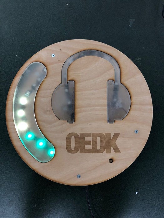
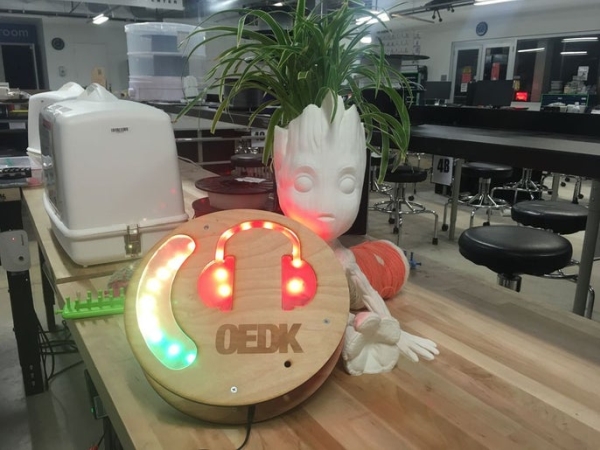
This device uses an Arduino Uno microcontroller. Analog sound data is received from a Gravity Sound Level Meter, averaged, and then used to trigger a digital LED strip output. The visual displays include a gradient that continuously displays the average decibel level and a set of headphones that flashes red once a predetermined decibel threshold is reached.
The casing is made from two plywood plates separated by two circular plywood plates separated by aluminum standoffs. The gradient and headphones displays are created with frosted acrylic All electronic components are mounted to the back plate.
From raw materials to being mounted on the wall, this device only takes less than 2 hours to complete. We learned a lot about data smoothing and controlling LED strips through this project and we hope you have fun building it!
Step 2: Components & Tools Needed
The total cost for materials for this device is a little under $100. Since our team is building this device en masse, we were able to buy some materials in bulk to reduce the cost. Also, since we are building this device for and in an engineering makerspace, we had access to a lot of the components and tools already.
The quantities of the components listed below are for one device.
Components
- 1x Arduino Uno (or similar microcontroller) with USB Cable
- 1x Prototyping Breadboard
- 1x Perfboard (optional)
- 2x Red Male-Male Jumper Wires
- 2x Red Male-Female Jumper Wires
- 2x Black Male-Male Jumper Wires
- 2x Black Male-Female Jumper Wires
- 3x Blue Male-Male Jumper Wires
- 2x Blue Male-Female Jumper Wires
- 1x 5V 1A Power Adaptor
- 1x Gravity Analog Sound Level Meter
- 1x Individually Addressable RGB LED WS2812B Strip (at least 20 LEDs)
- 6x Male-Male Header Pins
- 2x 330 Ohm Resistors
- 24” x 12” of 1/4″ Birch Plywood
- 7″ x 9″ of 1/4″ Acrylic
- 9″ x 9″ of 1/8″ Acrylic (width can vary)
- 3x 1/4″ Hex / 2″ 6-32 Female-Female Aluminum Standoffs
- 6x 1/4″ Hex / 1 1/4″ 6-32 Female-Female Aluminum Standoffs
- 18x 3/4″ 6-32 Flat-Head Screws
- 18x No. 6 Washers
- 8x 10mm M2.5 Female-Female Nylon Standoffs
- 4x 25mm M2.5 Female-Female Nylon Standoffs
- 4x 18mm M2.5 Male-Female Nylon Standoffs
- 24x 6mm M2.5 Screws
Tools
- Arduino IDE
- Soldering Iron (HAKKO FM-204) with Solder
- Rosin Flux
- Laser Cutter (EPILOG Fusion M2 40)
- Acrylic Glue
- Sandblaster (optional)
- Sandpaper
- 2-Part Epoxy
- Cordless Drill
- 5/32″ Drill Bit
- 1/8″ Drill Bit
- 1/2″ 82º Countersink Bit
- Drill Press
- #5 Counterbore Bit
- Screwdrivers
- Hot Glue Gun with Glue Sticks
Step 3: Prepare the LEDs
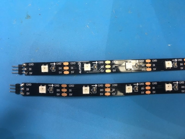
Cut two strips of the individually addressable LED strips at the markings on the strip. You can cut any number of LEDs you would like, just be sure to re-initialize the number of LEDs in the code later. We used 10 LEDs per strip.
Solder header pins onto each of the 3 connections one of the LED strip. Be sure to solder on the data input (DI) end. Repeat for the other LED strip. We used a bit of rosin flux brushed on the LED strip connectors to make soldering easier.
Bend and fold one of the LED strips into an arc-like shape to fit the curve of the gradient piece. We achieved this by creating a wavy pattern with the LED strip that could curve on itself. Using this same technique, shape the other LED strip to follow the curve of the headphones piece.
Step 4: Assemble the Circuit
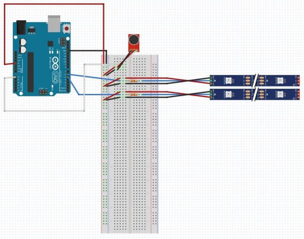
Start by connecting the Arduino 5V pin to the power rail on the breadboard. Then, connect the Arduino group pin to the ground rail on the breadboard.
Connecting the LED Strips
Connect the Arduino digital pin 5 to the data input (DI) connector on one LED strip, adding a 330 Ohm resistor between pin 5 and the DI connector. Connect the breadboard power rail on the breadboard to the 5V connector pin on the LED strip and connect the breadboard ground rail to the GND connector on the LED strip. This will be the LED strip for the gradient display.
Connect the Arduino digital pin 6 to the DI connector on the other LED strip, adding a 330 Ohm resistor between pin 6 and the DI connector. Connect the breadboard power rail on the breadboard to the 5V connector pin on the LED strip and connect the breadboard ground rail to the GND connector on the LED strip. This will be the LED strip for the headphones display.
Connecting the Gravity Sound Level Meter (the microphone)
Connect the Arduino analog pin A0 to the analog port on the Gravity Sound Level Meter. Connect the breadboard power rail on the breadboard to the VCC port on the Gravity board and the breadboard ground rail to the GND port on the Gravity board.
Transferring the Circuit to Perf Board (optional)
To keep all the electronic components in place longer, our team decided to move our circuit onto a perf board. Our circuit isn’t very complex, so we used a hacksaw to cut a 4cm x 6cm perf board into a 4cm x 3cm board and drilled new mounting holes into it with a 1/8″ bit. This step is completely optional.
Step 5: Edit and Upload the Code
Download the code and open it in the Arduino IDE.
Check that the value defined for the number of LEDs on each strip (NUM_LEDS_1 and NUM_LEDS_2) matches the number of LEDs you cut for the first LED strip (the gradient) and second LED strip (the headphones). If these values do not match, change the number on the code.
Verify and upload the code to your Arduino board.
Step 6: Prepare the Wood Casing
Download the wood laser cutting file.
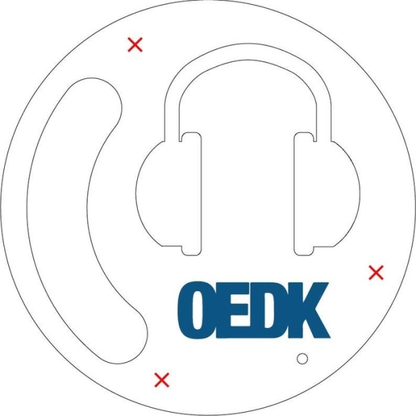
Laser-cut the front and back plates and 6 LED supports from 1/4″ plywood using the appropriate settings on your laser-cutter. Feel free to change the rastered logo on the front plate into any design you would like.
On our laser-cutter (EPILOG Fusion M2 40), we used the following settings:
- 4 speed, 100 power, 10 frequency to vector-cut
- 50 speed, 100 power, 300 DPI to raster-engrave
We used a laser-cutter because we have access to one on the OEDK, but you can also download the files to use as an outline to cut the pieces with a CNC router or bandsaw.
Drill 3 holes with a 5/32″ bit into the front plate in the locations shown by the red Xs in the image. There should be one hole between the gradient and headphones, one underneath the right headphone, and one underneath the logo. Countersink these holes from the front. These holes will be for the 2″ standoffs.
Lay the front plate on top of the back plate such that they are both oriented in the direction as seen in the laser cutting file. With a pencil, lightly trace the outline of the gradient and headphone spaces, the microphone hole and the 3 holes just drilled in the front plate onto the back plate.
Drill 3 holes with a 5/32″ bit into the back plate in the locations just transferred from the front plate. Countersink these holes from the back.
Step 7: Prepare the Acrylic Pieces
Download the 1/4″ acrylic laser-cutting file and the 1/8″ laser-cutting file.
Laser-cut the front-insert pieces from 1/4″ acrylic and the backing pieces from 1/8″ acrylic using the appropriate settings on your laser-cutter. On our laser-cutter (EPILOG Fusion M2 40), we used the following settings:
- 2 speed, 100 power, 100 frequency for the 1/4″ acrylic
- 4 speed, 100 power, 100 frequency for the 1/8″ acrylic
We used a laser-cutter because we have access to one on the OEDK, but you can also download the files to use as an outline to cut the pieces with a CNC router or bandsaw. Additionally, the backing pieces can be cut from acrylic of any width, but we found 1/8″ or thinner worked well enough for attaching to the wood while reducing weight.
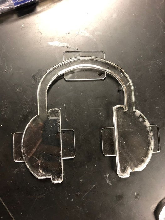
Glue each acrylic backing piece to its corresponding front-insert piece with acrylic glue such that when the front-insert pieces are placed into the front plate, the tabs on the backing pieces are flush with the back of the front face.
After the glue is set (at least 30 minutes), frost the front and back of the joined acrylic pieces to diffuse light better. We used a sandblaster for this, but fine-grit sandpaper (600 grit or higher) and some elbow grease will work as well.
Read more: Unsafe Noise Level Alert System