Summary of Arduino Fireflies
This project recreates backyard fireflies using an Arduino to pulse yellow LEDs like blinking insects. It covers required parts, weatherproofing for outdoor use, wiring LEDs to PWM pins (D3, D5, D6, D9, D10, D11) with one resistor per LED, and simple Arduino code using random timing. Notes include power choices (9V vs 4x AA), using Cat5 wire for long leads, and basic tools for enclosure assembly.
Parts used in the Arduino Fireflies:
- Arduino (Nano or any Arduino compatible microcontroller)
- Yellow 5mm LEDs (up to 6)
- Resistors (one per LED, example 470 ohm; anything above 150 ohm acceptable)
- Breadboard
- Jumper wire
- Weatherproof project box
- 9-volt battery with connector (or 4x AA battery holder recommended)
- Switch (waterproof recommended for outdoor use)
- CAT5 Ethernet cable (about 10 feet per LED for spacing)
- Small breadboard or perf board
- Weatherproof cable gland
- Heat shrink tubing
- Green hook-and-loop (velcro) strips
- Male headers
- Drill bits / step bit
- Hot glue gun
- Soldering iron
- Rotary tool (Dremel)
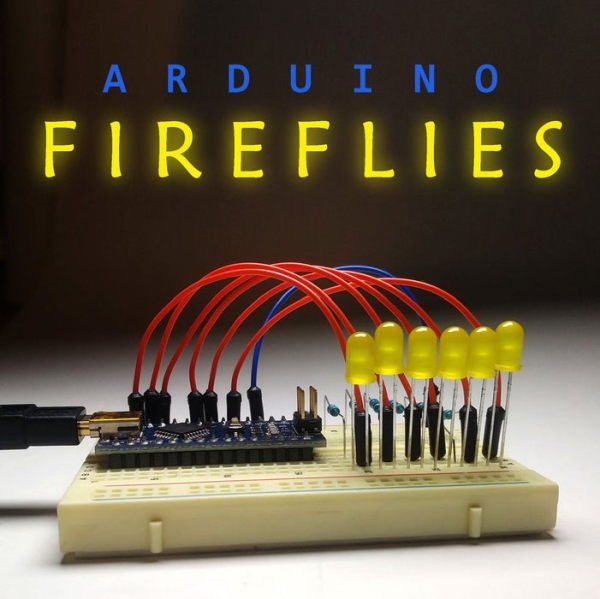
One of the things I look forward to with summers in Pennsylvania are fireflies in my backyard. I recently taught myself Adruino programming for the purpose of making this simple project. It’s a great program to start with and is easy enough for any programmer, novice to expert, to build, modify and have fun with in only a few minutes. Let’s get started.
Step 1: What You’ll Need.
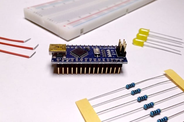
To get your bugs blinking, you’ll need these components:
- Arduino. I started with the Nano, however any Arduino compatible micro-controller will do.
- Yellow LEDs, 5mm. You can use up to 6 of them.
- Resistors. You will need one resistor per LED to limit current. I used 470-ohm but anything above 150 ohms should be fine to protect your micro-controller.
- Breadboard.
- Jumper wire.
To complete the project for your backyard, you’ll need:
- Weather proof project box.
- 9-volt battery with a connector. (Please see notes at the bottom of this section.)
- Switch. (I chose these waterproof switches. If you are not using this outside, any switch will do.)
- A few yards of wire to place the LEDs around the garden. I used about 10 feet of Cat5 Ethernet wire per LED.
- A small breadboard or some perf board.
- A weather proof cable gland through which the LED wires run. (You can omit this if you are not using this outside as well.)
- Heat shrink tubing to protect your LED bug butts.
- Green hook-and-loop (i.e. velcro) strips to affix the LED fireflies to plants and posts in your garden.
- Male headers for plugging components into your small breadboard.
Tools:
- Drill bits for the project box. (Use this opportunity to get yourself a nice step-bit. You’ll be glad you did).
- Hot glue gun.
- Soldering iron.
- Rotary tool (i.e. Dremel) for carving out space in the project box if you need it.
A Few Notes Here:
1. The battery choice was for a quick and easy start-up. Using a 9-volt battery permanently is a bit wasteful. You’re better off using a 4x AA-battery holder for longer life (however you will need a bigger project box in which to fit it).
2. If you choose to deconstruct a Cat 5 Ethernet cable for the wires, make sure they are copper core and wrap them neatly around some PVC to keep them organized while you work. Again, I used about 10 feet of wire per LED. If you want to spread the lights out far and wide, by all means use longer wires!
3. Lastly, all the links I provided are mere suggestions. Please read through this entire Instructable before building or buying anything as you will gain a better understanding of how you would like to personally proceed.
Step 2: Build the Circuit.
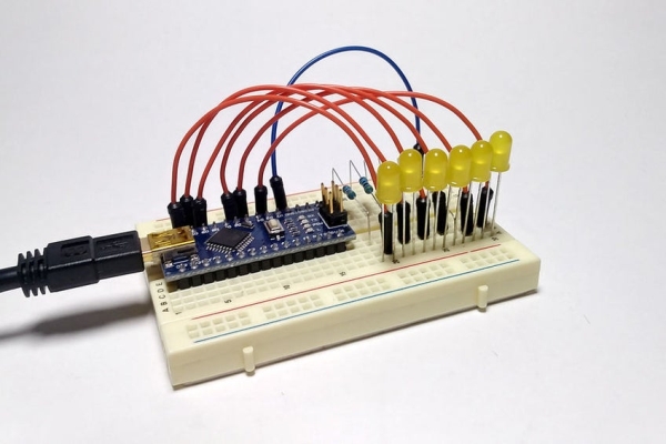
This project uses the pulse width modulation pins on your Arduino. The micro-controller has 6 of these pins and you are welcome to use as many as you want. The circuit is pretty straight forward. Wire all power from the pulse width modulation (PWM) pins D3, D5, D6, D9, D10, and D11 to the positive ends of your LEDs. Wire the negative ends to the resistors and then to a common ground. (The resistors can go in front of or behind the LED. It makes no difference unless you want to safeguard against short circuits in higher currents.) I included a few schematics to help with wiring. (The diagrams where created using Fritzing design software.)
Step 3: The Code.
If you are a seasoned programmer, you’ll find this code simplistic. It is a great code to start learning with as it introduces you to the use of variables, pinmodes, functions and even a random generator. The code is not as compact as it can be as I am sure the same effect can be achieved with arrays etc.
The code comments lay out the logic of each section. The entire code is embedded here and you may download the sketch below.
Read more: Arduino Fireflies
- What components are needed to build the Arduino fireflies?
Arduino (Nano or compatible), yellow 5mm LEDs, one resistor per LED, breadboard, jumper wires, power source (9V battery or 4x AA), switch, CAT5 wire for LED leads, weatherproof box and cable gland, heat shrink, hook-and-loop strips, male headers, and basic tools. - Can I use any Arduino for this project?
Yes, the author started with a Nano but says any Arduino compatible microcontroller will do. - How are the LEDs wired to the Arduino?
Wire each LED positive to PWM pins D3, D5, D6, D9, D10, and D11 and wire LED negatives through resistors to the common ground. - What resistor value should I use for each LED?
The author used 470 ohm; anything above 150 ohm should be fine to protect the microcontroller. - Is the project suitable for outdoor use?
Yes, with a weatherproof project box, waterproof switch, cable gland, and proper sealing the project can be used outdoors. - What power source is recommended?
The tutorial uses a 9-volt battery for quick startup but recommends a 4x AA battery holder for longer life. - Can I run LEDs far from the controller?
Yes; the author used about 10 feet of CAT5 wire per LED and suggests using longer wires if you want wider spacing. - Does the project use PWM pins on the Arduino?
Yes, the project uses the Arduino PWM pins to pulse the LEDs for the blinking effect. - Is the provided code complex for beginners?
No, the author describes the code as simplistic and suitable for learning variables, pinMode, functions, and random generation. - Do the instructions include soldering and enclosure preparation?
Yes, the build steps list soldering, drilling, and using a rotary tool for the project box among the required tools.