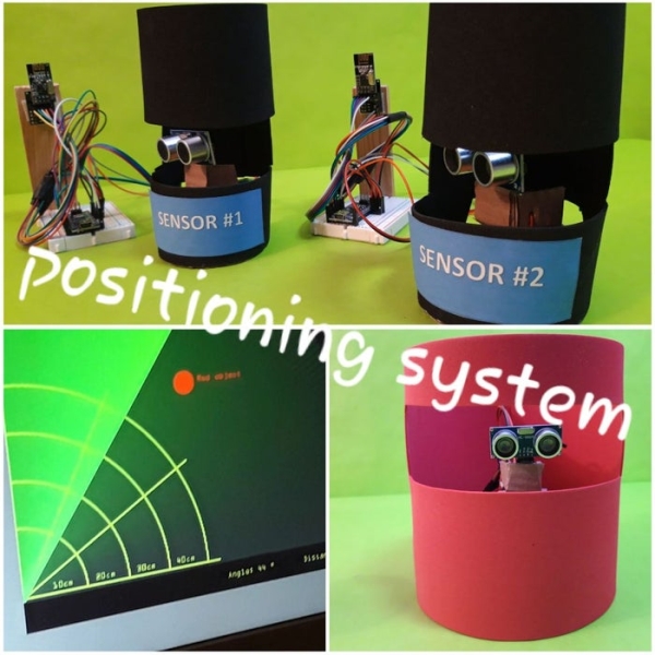
Summary of Ultrasonics Based Positioning System
This article presents an ultrasonic-based positioning system that identifies and locates objects without GPS. It uses three sensor stations and multiple object nodes, all equipped with ultrasonic sensors and wireless modules. The master station synchronizes measurements to avoid interference, collects distance and angle data, and calculates object positions using trigonometry. A Processing sketch visualizes the results, enabling real-time object identification and tracking in a defined area.
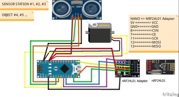
Parts used in the Ultrasonic Based Positioning System:
- Nano board
- Ultrasonic sensor
- Micro servo motor
- NRF24L01 wireless module
- NRF24L01 adapter
All the versions of ultrasonic radars I have found for arduino devices (Arduino – Radar/Ultrasonic Detector, Arduino Ultrasonic Radar Project) are very nice radars but all of them are “blind”. I mean, the radar detects something but what is it detecting?
So I propose myself to develope a system able to detects objets and identyfy them. In other words a positioning system without using GPS devices but ultrasonic detectors.
This is the result I hope you like.
Step 1: How Does It Work?
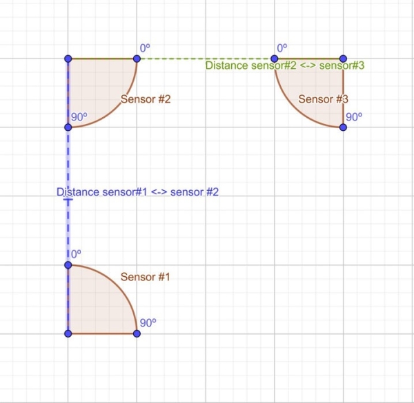
The positioning systems is formed by three sensors stations with ultrasonic detectors and id_node 1,2 and 3 forming a rectangle or square that sweep an angle of 90º and where the distances between them are known as shown on picture 1.
const float distancebetween1and2 = 60.0;
const float distancebetween2and3 = 75.0;
These sensors measurement the distance and angle of other objects with id_node greater than 3 that also have an ultrasonic detector that sweeps an angle of 170°.
All of them send the distances, angles measured and the id_node to another master station using wireless communicactions to analyze, calculate the position of the objects using trigonometry calculation and identify them.
To avoid interferences the master station synchronizes all the ultrasonics detectors in that way that only one ultrasonic detector is measuring at each moment
After that and using a serial communication the master station sends the information (angle, distance, id_object) to a processing sketch to plot the results.
Step 2: How to Configure the Three Sensor Stations and the Objects
The only function of each sensor station is to detect objects and send the list of distance, angle and id node measured to the master station.
So you have to update the maximum detection distance (“valid_max_distance “) allowed and the minimum one (“valid_min_distance “) (centimetres) to improve the detection and to limit the detection zone:
int valid_max_distance = 80;
int valid_min_distance = 1;
The id node of these sensor stations (“this_node” in the code below) are 1, 2 and 3 and the id node of the master station is 0.
const uint16_t this_node = 01;  // Address of our node in Octal format (Node01,Node02, Node03)
const uint16_t other_node = 00; //Address of the master node (Node00) in Octal format
Each sensor station sweeps and angle of 100º (“max_angle” in the code below)
#define min_angle 0
#define max_angle 100
As above the only function of an object is to detect objects and send the list of distances, angles and id object measured to the master station. The id of one object (“this_node” in the code below) has to be greater than 3.
Each object sweeps and angle of 170º and as above, it is possible to update the maximum and minimum detection distance.
const uint16_t this_node = 04;        // Address of our node in Octal format (Node04,Node05, ...)
const uint16_t other_node = 00;       // Address of the master node (Node00) in Octal format
int valid_max_distance = 80;
int valid_min_distance = 1;
#define min_angle 0
#define max_angle 170
Step 3: How to Configure the Master Station
The function of the master station is to receive the transmissions of the sensor stations and the objects and send the results using the serial port to a processing sketch to plot them. Moreover synchronizes all the objects and the three sensor stations in that way that only one of them is measuring at each time to avoid interferences.
Firstable you have to update the distance (centimetres) between sensor 1 and 2 and the distance between 2 and 3.
const float distancebetween1and2 = 60.0;
const float distancebetween2and3 = 70.0;
The sketch calculates the position of the objects in the following way:
- For all the transmissions of the objects (id_node greater than 3) look for the same distance in each transmission of the ultrasonic sensors (id_node 1, 2 or 3).
- All these points form a list of “candidates” (distance, angle, id_node) to be the position of one object (“process_pointobject_with_pointssensor” in the sketch).
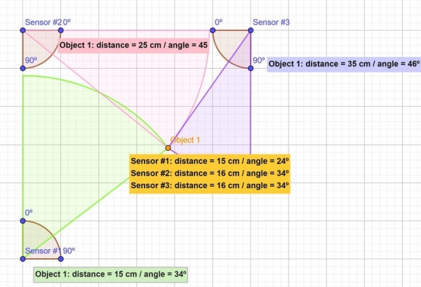
- For each “candidate” of the previous list, the function “candidate_selected_between_sensor2and3” calculates from the point of view of the ultrasonic sensor 2 and 3 which of them match the following trigonometry condition (see the pictures 2 and 3)
float distancefroms2 = sin(radians(angle)) * distance;
float distancefroms3 = cos(radians(angle_candidate)) * distance_candidate;

// Trigonometry condition 1
abs(distancefroms2 + distancefroms3 - distancebetween2and3) <= float(max_diference_distance)
- As above, for each “candidate” of the previous list, the function “candidate_selected_between_sensor1and2” calculates from the point of view of the ultrasonic sensor 1 and 2 which of them match the following trigonometry relation (see the picture 2 and 3)
float distancefroms1 = sin(radians(angle)) * distance;<br>float distancefroms2 = cos(radians(angle_candidate)) * distance_candidate;

// Trigonometry condition 2
abs(distancefroms1 + distancefroms2 - distancebetween1and2) <= float(max_diference_distance)
Only the candidates (distance, angle, id_node) that matches the trigonometry conditions 1 and 2 are identified objects detected by the sensor stations 1,2 and 3.
After that the results are sending by the master station to a processing sketch to plot them.
Step 4: List of Material
The list of material needed for one sensor station or one object is the following:
and the list of material for the master station is the following:
Source: Ultrasonics Based Positioning System
- How does the system identify objects?
The system identifies objects by calculating their position using trigonometry based on distances and angles measured by three synchronized sensor stations. - Can this system replace GPS devices?
Yes, the project is designed as a positioning system that operates without using GPS devices but relies on ultrasonic detectors. - What prevents interference between sensors?
The master station synchronizes all ultrasonic detectors so that only one detector measures at each moment. - Does the master station calculate positions?
Yes, the master station analyzes received data to calculate the position of objects using trigonometry calculations. - How are sensor stations configured?
Each sensor station has a unique ID (1, 2, or 3), sweeps a 100-degree angle, and sends distance, angle, and ID data to the master station. - What angle do object nodes sweep?
Object nodes have an ID greater than 3 and sweep an angle of 170 degrees. - How is the final result displayed?
The master station sends the calculated information via serial communication to a Processing sketch to plot the results. - What materials are needed for the master station?
The master station requires a Nano board, an NRF24L01 wireless module, and an NRF24L01 adapter. - What trigonometric conditions are used for identification?
The system checks if the sum of calculated distances from sensor pairs matches the known distance between those sensors within a maximum difference margin.