Hello!
My name is David, I am a 14-year-old boy living in Spain and this is my first Instructable. I have been building robots and fixing old computers for some time now and my robotics teacher told me that it was good time to start sharing with other people what I have learnt. So here we go!
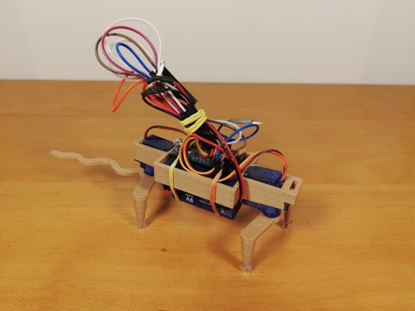
One day a friend of mine gave me a 3D model to build a robot and some components: One arduino nano microcontroller and two servo motors, with these 3 things I started to build my little robot.
In this Instructable I am going to share with you how to make this robot, also I will include the 3D model and the code that I have written, so you can have all that it is needed to make your own robotic rat!
Step 1: What You Need:
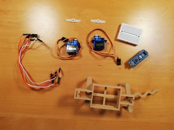
– Arduino Nano microcontroller
– 2 SG90 servo motors (You can find them in Amazon, or in some online shops)
– You will have to print the 3D model or you can build a structure with cardboard or plastic. I used this model: https://www.tinkercad.com/things/12eU8UHtMSB from Tinker Robot Labs
– Some wires, and a small breadboard
– A 9 Volt battery and a connector
Also you will need to use the arduino IDE, you can download it in the next link: https://www.arduino.cc/en/Main/Software
Step 2: Calibrating the Servos
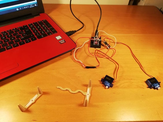
Before starting the robot you have to do one previous step. You need to find the middle position of the servo. A servo can turn 180 degrees (half a circumference), and you need to find where is the 90 degree position first to be able to put the legs perpendicular to the body. To do this I wrote a program that puts the servos in the 90º position. Once the servos are at 90º you will have a reference point of where the servo will be at the beginning of the program.
This is the program that I use to center the servos:
#include
Servo Front;
Servo Back;
void setup() {
Front.attach(9);
Back.attach(6);
}
void loop(){
Front.write(90);
Back.write(90);
}
You will have to make small adjustments to the software or the hardware to improve the movement of the robot and get a perfect gait, but first let’s make the robot move, and at the end of the project, you will be able to do these adjustments.
Step 3: Assembling the Legs
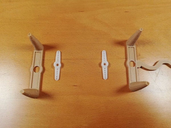
After this you have to take the shafts of the servos and put it into the legs of the robot, to make this easier you can cut a little of the material around the hole in the legs to enter there the shafts.
Secondly you will need to screw in the shafts with the 3D legs into the servos, when you have all in the right position, put a little dot of hot glue between the shaft and the legs to secure them in place. Be sure to put the legs at 90 degrees as seen in step 2.
Step 4: Installing the Servos
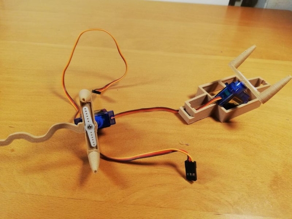
Now you have to install the servos in the body of the robot, to do this you have to take the body in one hand and push in the servo, with the legs, into a hole that you have for the servo. Be sure that the wires of the servo goes in the right position, if not the servo will not fit in the chassis. There is a small slot on one of the sides of the servo hole. Use that slot for the wires.
Repeat this step with the other set of legs.
Step 5: Adding the Arduino
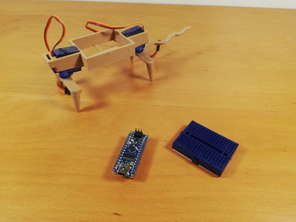
After all these steps you will have the robot hardware finished. Now we are entering in the final part, the electronics and wiring. First, take the Arduino Nano and push it into the breadboard, then you’ll have to remove the paper in the bottom side of the breadboard and glue the breadboard in the 3D model.
Step 6: Wiring
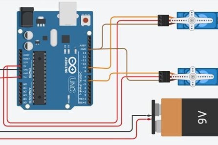
Let’s do the wiring! In this step in which you will connect all the wires from the breadboard, to the servos.
All the servos have three wires, so one is for the information that the arduino sends, the orange one, other is for the +5v current, the red one, and finally the GND (or ground) wire, that is the brown one.
To connect the wires you may want to look at the code we have used to center the servos. In the code we can see that the servo for the front legs it is connected to the pin D9 and the other servo, the one for the back legs and tail it is connected in the port D6. this means that the orange wire of the front servo goes to the D9 pin, and the orange wire of the servo for the back legs is connected to the D6 pin. The red cable of both servos go to 5V and the brown wires of both servos go to GND (any of the GND pins of the Arduino Nano).
Source: Robotic Rat