Summary of ADS1115 InstESRE Pyranometer
This article details the construction of a modified InstESRE pyranometer kit for measuring solar irradiance. The project integrates an Arduino with an ADS1115 analog-to-digital converter and includes a TMP36 temperature sensor for data correction. The build process involves preparing an enclosure, assembling a PDB-C139 photodiode with a Teflon diffuser, and optionally installing the temperature sensor using superglue. Documentation is available via GitHub for software and step-by-step instructions.
Parts used in the Modified InstESRE Pyranometer:
- InstESRE pyranometer kit
- Arduino microcontroller
- ADS1115 analog-to-digital converter
- TMP36 temperature sensor
- PDB-C139 photodiode
- Teflon diffuser disk
- Housing tube
- LED holder
- Enclosure case
- Grommet
- Bubble level
- Superglue
- Tape
A pyranometer measures the sun’s irradiance (power/area, basically “brightness”) on a surface. Despite the similar names, it is completely different from a pyrometer, so stop right here if that is what you are looking for.
This Instructable describes how to build and test a modified version of the pyranometer kit offered by Dr. David Brooks of the Institute for Earth Science Research and Education (InstESRE):
http://www.instesre.org/construction/pyranometer/pyranometer.htm
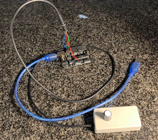
This version of the InstESRE pyranometer interfaces with an Arduino using an ADS1115 analog-to-digital converter (ADC) and also supports temperature correction using a TMP36 temperature sensor co-located with the photodiode.
The IV Swinger 2 IV curve tracer supports this pyranometer design as an optional sensor, and that was the motivation for the modifications. However, since other users of the InstESRE pyranometer may find it useful, this Instructable describes the design independently from the IV Swinger 2 project.
The following GitHub repository contains the documentation and software:
https://github.com/csatt/ADS1115_InstESRE_Pyranometer
Please download and read the document before proceeding. The document contains a text-only version of the steps in this Instructable and can be used as a checklist during construction. It also describes how to order the kit from Dr. Brooks and what additional parts to buy. Those are not repeated in this Instructable.
Step 1: Gather Tools
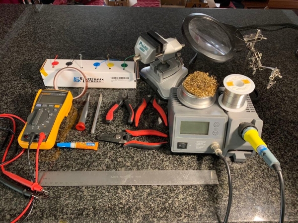
I used the tools shown in the photo.
Step 2: Prepare Enclosure
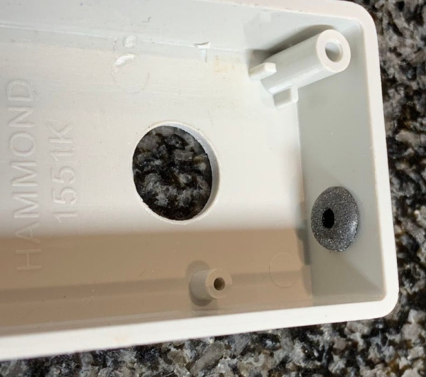
- Insert the grommet into the hole at the end of the case. Use a small blunt object such as a small screwdriver. Be careful not to cut the grommet. (The grommet is the soft rubber O-shaped item.)
_______ - Spread a small amount of superglue around the inside of the larger of the two holes in the top of the case. Insert the bubble level from the inside of the case. Make sure the bubble level’s shoulder seats firmly against the top of the case. Set the case aside, upside down, to let the glue dry for several minutes.
[NOTE: the bubble level is not needed for the IV Swinger 2 application, and it is not shown in the photos.]
Step 3: Prepare Photodiode and Diffuser
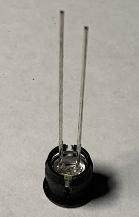
- Make sure the PDB-C139 photodiode leads are straight and parallel to each other, making adjustments if necessary.
_______ - Insert PDB-C139 photodiode into the LED holder. It should snap into place. Do NOT use any superglue.
_______ - With the PDB-C139 photodiode leads pointing up and with the longer lead to the left and the shorter to the right, VERY SLIGHTLY bend both leads away from you.
_______ - Insert the photodiode assembly into the housing tube from the top. Again, do NOT use any superglue. Make sure the top of the diode is clean and dust free.
_______ - Pick up the Teflon diffuser disk with a paper towel or tissue and rub both surfaces gently to remove any dust or debris that might be there. Snap the disk into its recess at the top of the housing tube. Do NOT use any superglue. If it is a very loose fit, you will have to use some superglue LATER, but NOT YET.
_______ - Flip the assembly upside down (leads pointing up, longer one to the left). Make sure the diffuser disk didn’t fall out. Use 4 pieces of tape to hold it down on a hard, smooth work surface. The tape should be below the machined rim of the tube. Wrap one more piece of tape around the tube.
Step 4: Add TMP36 (optional)
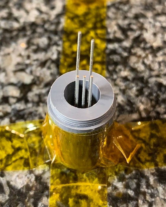
- Insert the TMP36 into the hole on the near side of the photodiode leads, with the flat side of the TMP36 toward the leads, and the rounded side towards the wall of the tube. Press it down by the ends of its leads. It should fit nicely with minimal deflection of the photodiode leads.
_______ - Remove the TMP36, apply superglue to its top, flat side, and rounded side and promptly insert it back into the hole in the same position. Use only enough glue so it should stick to the LED holder, diode leads, and inside of the tube, but don’t use so much that it could possibly flow around the photodiode. Make sure to press it into the hole quickly, so the glue doesn’t grab it before it is all the way in.
_______ - Adjust the two photodiode leads and the three TMP36 leads so they are all pointing as straight up as possible
Source: ADS1115 InstESRE Pyranometer
- What is the primary function of this device?
A pyranometer measures the sun's irradiance or brightness on a surface. - How does this version differ from the original InstESRE kit?
This version interfaces with an Arduino using an ADS1115 ADC and supports temperature correction with a TMP36 sensor. - Can I use a bubble level if I am building this for the IV Swinger 2 application?
No, the bubble level is not needed for the IV Swinger 2 application and is not shown in the photos. - Where can I find the documentation and software for this project?
The documentation and software are located in a GitHub repository at https://github.com/csatt/ADS1115_InstESRE_Pyranometer. - Should I use superglue when inserting the photodiode into the LED holder?
No, you should NOT use any superglue when inserting the PDB-C139 photodiode into the LED holder. - How do I prepare the Teflon diffuser disk before installation?
You must pick up the disk with a paper towel or tissue and gently rub both surfaces to remove dust or debris. - What is the correct orientation for the TMP36 sensor leads?
Insert the TMP36 with the flat side toward the photodiode leads and the rounded side towards the wall of the tube. - Is it necessary to order additional parts directly from Dr. Brooks?
Yes, the guide describes ordering the kit from Dr. Brooks and buying additional parts separately as they are not repeated in the text.