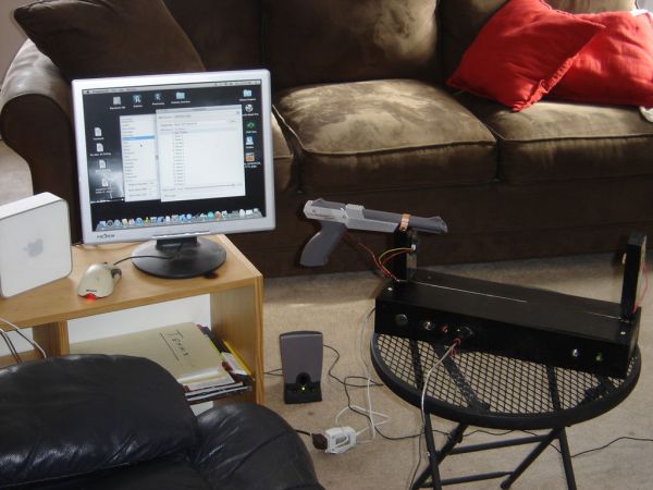
I created this Theremin like device after seeing this article in Make magazine: http://m-cdn.dashdigital.com/make/vol15/?pg=69#pg67
While this looked pretty straight forward it turned out to be a bit much for me at the time. But after much effort, I got it to work pretty good.
I had trouble getting the laser to aim correctly so I chose to mod a zapper I had available to hold the laser. This worked well.
So I will recap the steps:
Step 1: Video of finished and working
Here I am randomly choosing different styles .
I expect it would work nicely with any other midi player.
Step 2: Get stuff
Parts that are needed:
Basically I used the parts list that is on the first page of the Make Magazine article. But that list is for the harp which has 6 lasers so most quantites can be just 1..
1. Arduino – I used a Diecimila
2. Inexpensive laser pointer – I got a red one from eBay for a couple of dollars
I was hoping to be able to see the laser but have learned that red will not show up unless it is quite powerful.
So it might be better to have a green laser instead of red.
3. Power Source – I used an AC adapter that I had . It outputs 12Volts and 1.7 Amps.
4. Adjustable voltage regulator – used the Trossen #P-VR-DE-SWADJ
5. 5V – 7805 voltage Regulator – I got from Jameco – pn 51262
6. LM324 quad op-amp chip – Jameco – 23683
7. Red LED – I had – can get from Radio Shack
9. Resistors – 220 ohm
– 1.5K
– 3.9k
– 68 K
– 1M
10. Photocell – 100mw – jameco – 202403
11. IR range sensor – Trossen – GP2D12
12. tumbled rock – Hobby Lobby
13. potentiometer – 100k – jameco – pn29103
14. 5 pin DIN MIDI connector – jameco pn 15844
15. circuit boards – radio shack
Also a midi cable to connect the Theremin to a MIDI device eg a computer running software that can interpret MIDI input. I got one from eBay for about 10.00.
Step 3: Schematics
The Make article refers you to this link http://makezine.com/15/laserharp/ . You can then download a zip file with schematics. I have photoed them and attached here.
As I am new to this I had to do a lot of head scratching and trial and error to get things working . But I believe i learned a lot.
Step 4: Building it – Power Supply
I did bread board this but I did not take pictures at that time .
To make it simpler for me to understand, I separated the major parts onto separate circuit boards.
It seemed to make it easier to follow the flow of the schematics, at least for me.
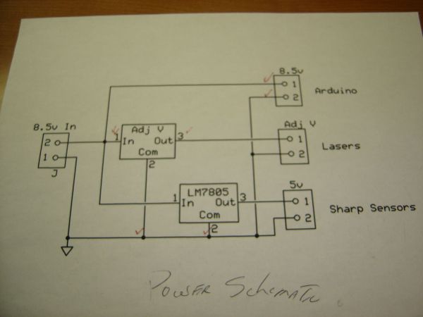
The Power Supply:

Basically;
8.5V goes directly to the Arduino to power the Arduino.
8.5 V goes directly to the Trossen adjustable voltage regulator. After the rest of the wiring is done, you adjust the regulator to output just enough voltage to turn the laser on.
8.5V goes to the LM7805 which outputs 5v to go to the Sharp sensor
2. Inexpensive laser pointer
3. Power Source
4. Adjustable voltage regulator
For more detail: Theremin with Zapper,laser,Arduino

