Summary of The KITT-duino, DIY Larson Scanner with an Arduino
This article details a DIY Larson Scanner project using an Arduino, inspired by the Knight Rider TV series. The guide covers designing a custom LED sequence where lights move in complex patterns (sides to middle and back) rather than just side-to-side. It provides step-by-step instructions for preparing wires, assembling components on a perf board, and soldering connections safely. The author emphasizes code modifiability and invites community feedback for improvements.
Parts used in the KITT-duino Larson Scanner:
- 10 5mm LEDs
- 10 220 ohm resistors
- 1 Perf board
- Solder
- Soldering Iron
- CAT5 wire or 22 AWG wire
- Wire stripper
- Wire cutters
- Arduino board
IMPORTANT: CODE IS NOW UPDATED. FIXES INCLUDE ADDING AN INTEGER VALUE TO MANIPULATE TIMING AND FIXING A DOUBLE-BLINKING LED.
Thanks.
It is my understanding that many Larson Scanners can only pulse from side to side. I felt that that needed to be changed, seeing as that in the newer (yet short-lived) Knight Rider series revival on NBC for about 1/2 of a real season, the iconic red lights would move from right to left and back, start on both sides to meet in the middle (and then return), go from left to right and back, to middle, and then repeat… I drew out in sequence how the LEDs will light up. The arrow indicates the direction the LEDs will light up.
This simple project for the Arduino will produce pretty good results for the time and money, and the code can be modified very easily, which will be detailed later…
Please share improvements on the code with me, this is my first Arduino project (other than the “Blink” tutorial) so I’d enjoy hearing where it could be better.
Now… Onto the materials list.
Also, please rate and comment if you have a minute. It is all very much appreciated.
Board Prep
To begin, plug in the Soldering Iron.. Let it heat up until you complete the following
1- Take the CAT5 wire, splice it down the side, and separate in into a bunch of little insulated wires.
OR,
1a- Cut the 22 AWG into 6 inch lengths
2- Strip one end of the wire to about 5mm copper showing. Strip the other ends at about 3mm. Repeat for a total of 11 wires
3- Snip the leads of the Resistors and the down a little so they are easier to work with on the board. DO NOT CUT THE LEDs… If you do, there’s no easy way of telling anode from cathode
( + from – ) because from the factory, each LED has a long leg and a shorter leg. Shorter= negative, longer = postive.
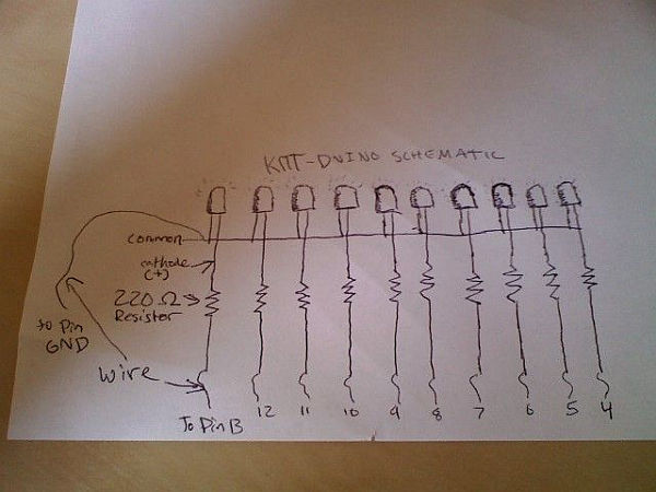
FOR THE NEXT STEPS… I drew up a schematic and put a picture of it so if it will help you, that is how it is on the board.
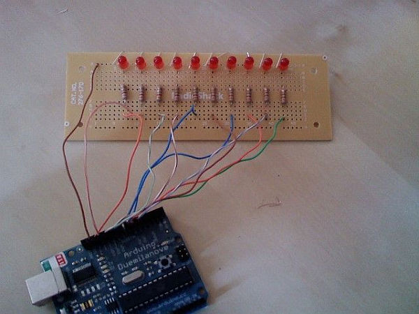
4- Insert the LEDs into the board as shown. The actual gap between them is up to you. Every 3 holes worked for me. Fold the leads down to keep it in place. Make sure the negative side is going through a hole that is plated onto a long strip to connect with all other LED anodes.
5-Insert the one side of the resistor into a hole that is VERTICALLY inline with the cathode of each LED. Insert the other end in a hole that is over the gap with no holes. Make sure it isn’t the bottom one. Bend the leads to make it stay.
6- Insert the little wires into the perf board by the 3mm stripped end, one below each resistor. This size will solder well and the 5mm side will fit into the pins on the Arduino. Tape these on, there won’t be enough copper to bend it very well.
TIP- Alternate colors of wire (if using CAT5) so it is easier to troubleshoot connections later.
7- Insert one wire as a common lead at the top of the board connected to the anodes.
8- If it similar to the picture, flip it over (or put in some gentle sort of vise) and prepare to solder.
Soldering and more soldering
By now, the soldering iron should be very toasty. We’d better put it to use right about now…
Make sure all of the LEDs are parallel so they won’t look zig-zaggy or something weird when they set. I “trued” mine to a tabletop side
Then, solder all connections, taking care not to join any lead to a copper conductor except the one it should be at. See picture for clarification. I connected some of the leads with solder and the built in copper conductors. Like I said, I am not very good at soldering so if you are, don’t make the globs of solder so large. Note how the resistors are inline with the LEDs and in line with the small wire. This is key to the project so that when the Arduino turns one pin on, the other LED won’t turn on by mistake…
DISCLAIMER- The board, joints, and leads will get very hot!!! Don’t try to move anything on the board with your hands while there is hot solder on the board if you can help it.
Materials needed:
10 5mm LEDs, any color (I chose red in true KITT style and bought them for about $.05 a piece)
10 220 ohm resistors (Radio Shack part no. 271-1111)
1 Perf board (Radio Shack part no. 276-170)
Also,
Solder
Soldering Iron
1 ft CAT5 wire or 5.5ft 22 AWG wire
Wire stripper
Wire cutters
And of course, an Arduino. I used a Duemilanove for mine.
For more detail: The KITT-duino, DIY Larson Scanner with an Arduino
- How can I modify the LED movement pattern?
The code can be modified very easily to change how the LEDs light up. - What is the best way to distinguish LED polarity?
The shorter leg is negative and the longer leg is positive. - Does the project require expensive materials?
No, it only requires about $4.50 USD in materials. - How long does it take to build this project?
It takes about 3 hours if you do not know how to solder well, or under an hour if you are skilled. - Can I use CAT5 wire instead of 22 AWG wire?
Yes, you can splice CAT5 wire down the side or cut 22 AWG into 6 inch lengths. - What should I avoid cutting during preparation?
You should not cut the LEDs because factory legs indicate anode and cathode. - How should I strip the wires for connection?
Strip one end to about 5mm copper showing and the other ends at about 3mm. - Why must I alternate wire colors when using CAT5?
Alternating colors makes it easier to troubleshoot connections later. - What safety precaution is needed during soldering?
The board, joints, and leads get very hot so do not move anything with your hands while hot.