
Summary of SMS controlled Wireless Irrigation System using an Arduino
This article details the construction of an SMS-controlled wireless irrigation system designed to remotely manage water pumps, detect motor jams, and send error alerts. The project aims to solve the difficulty of monitoring irrigation systems manually by using a GSM network for control and notification, ensuring cost-effectiveness under $150 while protecting equipment from electrical faults.
Parts used in the SMS controlled Wireless Irrigation System:
- GSM mobile phone with SMS feature
- Activated GSM SIM/micro-SIM card
- Miniature Circuit Breakers
- 30 Amp Relays (120v/240v)
- Atmega 168/328p or Arduino microcontroller
- 9v Power Supply
- Universal charger
- High-Gain external antenna (optional)
- FIRE-PROOF wires
- Terminal blocks
- Spade connectors
- Enclosure
- 1N4001 diodes
- 2n2222, TIP31, and TIP102 transistors
- 1K resistors
- Miniature Push Switches
- Perfboard
- Misc. LEDs
- 5v coil relays
UPDATE 02/13/11 : Voting has started for the Sparkfun Microcontroller Contest. Please VOTE for me!
UPDATE 02/26/11 : I won a second prize!! Huzzah! Thanks for all the votes guys!
UPDATE 03/17/11: I would love to win a Laser cutter in the Epilog challenge as it would help the small DIY community in Calcutta, which just started a few months back to cut all their materials using a CNC instead of using their saws etc.
Irrigating crops with the exactly right amount of water is a tedious task, especially when you have to walk a long distance to the irrigation pump in the middle of the night to check whether any problem (fish getting stuck in the intake and as a result the irrigation motor burning or jamming!) has occured. As I saw my uncles tired of doing the same, I felt there had to be some remote controlled solution to their problems.
I started to think about a system, which would:
1. Detect jamming of the motor and immediately shut it down.
2. Be cost effective.(Less than $150)
3. Remotely turn on and off the irrigation motor.
4. Send back a message to the operator, if an error occured.
And thus came the brainstorm to build the “SMS controlled Wireless Irrigation System” . I also wanted to submit this to the Sparkfun Microcontroller Contest , so it was all the more reason for me to go straight to building the prototype.
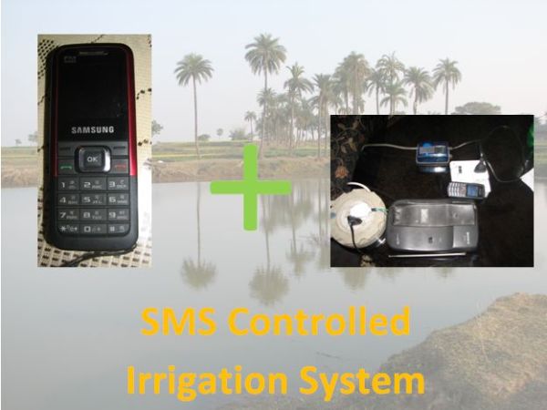
The prototype could do the following:
1. Be remotely controlled via SMSs through a cellular GSM network.
2. Send back ERROR messages to the operator, if the Miniature Circuit Breaker (MCB) was tripped due to electrical faults or motor jamming.
3. Control loads of up to 15 amps.
The fruits of my work is detailed in this ible.
P.S I suggest that you read through the entire Instructable before starting.
Step 1: Getting the Materials
For this project we need various cheap parts and you should be able to get these easily at any local Radio Shack. We only need a few extra parts which you might have to go to another shop. The bill should total at max. $100. You must think I’m joking but I’m not. At India, we get stuff even cheaper – Rs.1000 ($40 approx.) max.
Parts List:
Hardware Parts:
1. 1x cheap/old/used GSM mobile phone with SMS feature(with charger)
2. 1x Activated GSM SIM/micro-SIM card of your preffered provider
3. 1x Miniature Circuit Breakers
4. 1x 120v/240v(choose for your country) 30 Amp Relays
5. 1x Atmega 168/328p or an Arduino (OR any other micro with which you are friendly)
6. 1x 9v Power Supply for the Arduino/Atmega etc.
7. 1x Universal charger if you don’t have a phone charger
8. 1x High-Gain external antenna(optional)
9. Wires (240v/120v FIRE-PROOF wires) and some scraps for the circuit-board
10. 2x 240v terminal blocks
11. 4x spade connectors(for the relays)
12. 3x terminal blocks
13. A enclosure(to encase the electronics) like http://www.pactecenclosures.com/product-detail.php?classid=35&seriesid=38&productid=231
Electronics Parts:
1. 10x 1N4001 diodes
2. 4x 2n2222 transistors
3. 2x TIP31 transistors
4. 3x TIP102 transistors
5. 10x 1K resistors
6. 2x Miniature Push Switches
6. 1x Perfboard (not if you make a PCB)
7. 1x Pack of Misc. LEDs(small size)
8. 5x relays with 5v coil
Tools Needed:
Multimeter
Soldering Iron
Screw Driver
Drill (with drill bits)
Sander 😉 see (http://www.instructables.com/id/Recycled-HDD-Rotary-Sander-for-5/)
Step 2: Assembling the Mains Circuit
WARNING: This project uses High Voltage AC mains voltage and could cause death or electrical shock, so I am not responsible for any damage you do to yourself or to others around you. Proceed at your own discretion and if you are NOT comfortable doing this part yourself, get it done by a qualified electrician.
This project uses a high voltage relay(30 Amps and 240v)to control the irrigation pump.The mains circuit is housed in a separate enclosure and consists of the Miniature Circuit Breaker, A wall socket and a resettable cartridge fuse (the ones where a button pops out).
You will have to wire up the mains line as shown in the below diagram, basically like this:
Power Plug——– Electronics controller ——- MCB——– Wall Socket
After connecting everything up, make sure to route the wires and put the entire setup in a separate junction box with a few ventilation holes drilled in the sides,with the MCB and wall socket showing on top.
Step 3: Making the MCB State-Detection Sensor
The MCB state-detection sensor is basically a custom switch, which detects whether the MCB is in its tripped position or not. Accordingly the Arduino takes the steps to send the error SMS to the pump operator.
It consists of two screws, which are placed in such a way that the switch is closed when the MCB trips. One screw is mounted on the MCB’s face plate and the other is mounted on the MCB’s plastic switch. The diagram below clearly explains how I did it.
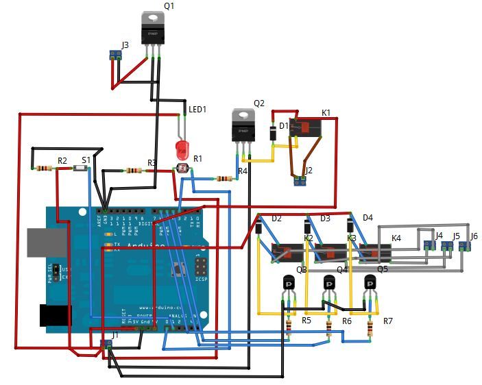
Attach one wire to Analog 2 on the Arduino , the other one to 5v on the Arduino, placing a 1K pullup resistor at the junction and attach the other leg of the resistor to the common GND on the Arduino. Step 5 shows this properly, in the form of a circuit diagram.(2nd picture)
Power Supply for the Arduino
Universal charger
For more detail: SMS controlled Wireless Irrigation System using an Arduino
- How does the system detect motor jamming?
The system uses a custom MCB state-detection sensor that acts as a switch closed when the Miniature Circuit Breaker trips due to electrical faults or motor jamming. - Can I remotely turn on and off the irrigation motor?
Yes, the prototype allows remote control via SMS through a cellular GSM network. - Does the system send error messages to the operator?
Yes, it sends back ERROR messages if the MCB is tripped or if an error occurs. - What is the maximum load this system can control?
The system is capable of controlling loads of up to 15 amps. - Is this project cost-effective?
Yes, the total bill should be at most $100, or around Rs.1000 ($40) in India. - What safety warning is associated with this project?
The project uses high voltage AC mains voltage which could cause death or electrical shock, so a qualified electrician should be consulted if uncomfortable. - Which microcontroller is recommended for this build?
An Atmega 168/328p, an Arduino, or any other microcontroller you are friendly with can be used. - How is the MCB state detected electronically?
A wire is attached to Analog 2 on the Arduino and another to 5v, with a 1K pullup resistor connecting the junction to common GND.
