Summary of Proteus Tutorial – Light Emitting Diode (LED) and Bar Graph Display
This article explains how to use Light Emitting Diode (LED) components in Proteus, including locating LEDs in the Optoelectronics library, editing component properties (forward voltage/current, model type, self-flashing), calculating series resistors, wiring for simulation, and using bar graph displays. It shows steps to pick, place, edit and simulate LEDs and bar-graph LED displays, and summarizes typical 5mm LED specifications and safe operating practice.
Parts used in the Light Emitting Diode (LED) in Proteus:
- LED (various colors/types from Optoelectronics library)
- Resistor
- Battery (Vsource)
- Digital IC or microcontroller (when driving digitally)
- Op-amp or potentiometer (when driving analog)
- Self-flashing LED (optional)
- Bar graph display
- 10 Way common element DIP switch
How to work with Light Emitting Diode (LED) in Proteus
In this post, we will be learning how to use the “Light Emitting Diode (LED)” component in Proteus simulation software. In case you have not got on through the basics of Proteus, here is the link – Proteus PCB Design and Simulation Software – Introduction.
Note:- You may also read our 1st chapter on Proteus Tutorial Series – Switches and Relays in Proteus before you continue reading this chapter.
Types of LEDs available in Proteus
Proteus contains LEDs of different colors and types that are being used in real-time applications.
LEDs are found in Proteus software under the Library category Optoelectronics. Remember to select ‘ACTIVE’ components so that the simulator provides a real-time interface during simulation.
- Step 1: Select component mode.
- Step 2: Click on Pick devices ‘P’.
- Step 3: Scroll down categories to find ‘Optoelectronics’ or alternatively type LED in Keyword. Select
this category and it shows the available LEDs in the result. - Step 4: Scroll to find the required LEDs according to the circuit.
- Step 5: Remember to select components with the ACTIVE property under the Library column of the search
results for interactive simulation.
Component Properties of LEDs
The technical parameters of the LEDs like forwarding Voltage Drop and Forward Current are set to default values. One can change them according to the LED that is being used in the actual circuit in real time i.e., Voltage Drop and current which vary according to the color and size of the LED.
This table shows the Specifications of 5mm LEDs:
| S.No. | Color of LED | Forward Voltage Drop(V) | Forward Current (mA) |
| 1. | Green | 2.0 | 25 |
| 2. | Red | 2.0 | 30 |
| 3. | Yellow | 2.1 | 30 |
| 4. | Blue | 3.5 | 30 |
These are typical Specifications of LEDs given by a manufacturer. These may vary slightly depending on the manufacturer and test conditions.
To change the properties of the LEDs:
Step 1: Place the component in the workspace.
Step 2: Right-Click on the component and select Edit Properties or double-click on Component.
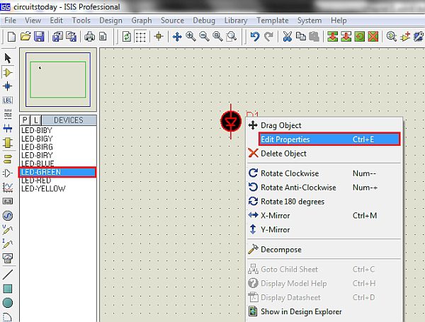
Step 3: Change the Properties as per type of LED.
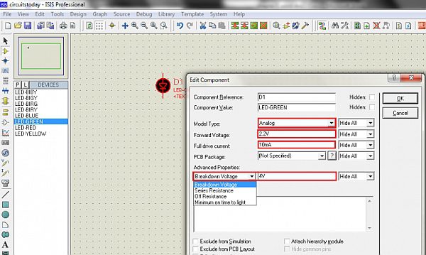
Model Type parameter is chosen according to the type of input given to the LED. For example, if the LED is driven by a Digital IC or a microcontroller it can be set to Digital. If the LED is driven by an OP-Amp or a potentiometer it can be set to Analog. For self Flashing LEDs there is an option to enable or disable self-flashing in Edit Properties.
Using LEDs in Circuits
LEDs must be powered with voltages under specified limits, so that safe current flows through it without damaging. It is better to use a series resistance to ensure it is under Safe Operating Area(SOA).Formula to calculate series resistance is
Rs = (Vsource–Voltage drop of LED)/(Maximum Forward Current)
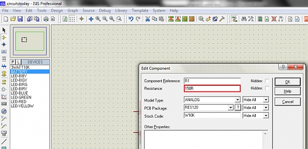
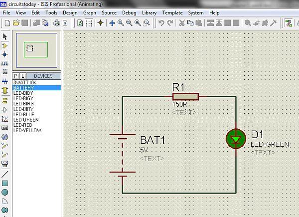
Applying this formula to LED of 2 Volts drop and 20mA forward current for a source voltage of 5Volts, gives series resistance of 150 Ω.
Rs = (5-2)/0.02 = 150 Ω
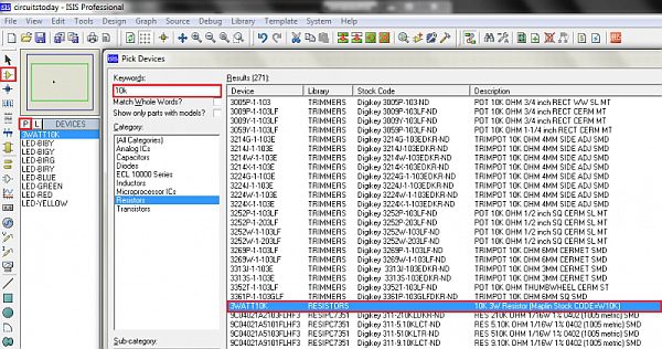
Step 1:Choose necessary parts such as Battery, LED and resistor. If you cannot find the exact resistor value needed, select a different value and adjust its resistance in the Edit Properties Tab. Resistor wattage is not a concern during simulation unless PCB design is being planned. In hardware implementations, the selection should be based on LED type and input voltage.
Step 2: Right-Click on the component and select Edit Properties or double-click on Component.
Step 3: Place the components and connect as per the circuit diagram and run simulation.
Bar Graph Display and its Application
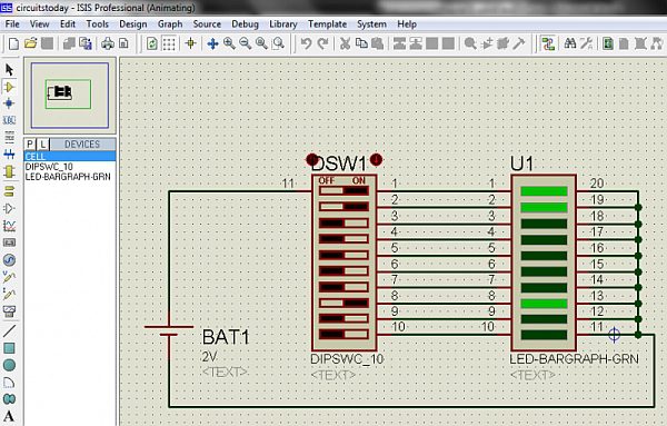
Bar graph displays are Rectangular shaped LEDs arranged one above the other in standard package styles. This type of displays can be used to indicate the level of a signal (Temperature, Noise etc..,) or current status of a process that involves multiple steps etc..,
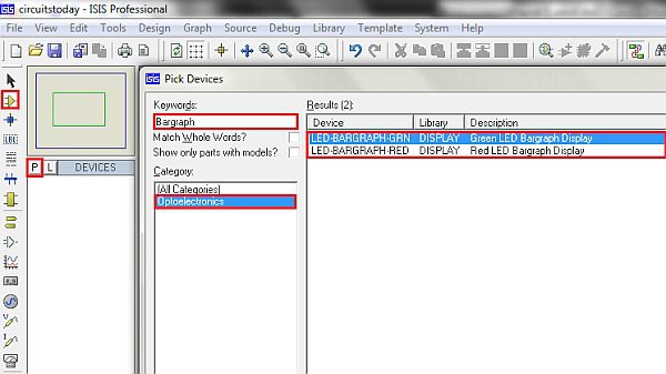
Bar graph displays are found in Proteus software under Library category Optoelectronics.
Step 1: Select component mode
Step 2: Click on Pick devices ‘P’.
Step 3: Type Bar graph in the Keyword textbox and select the required display.
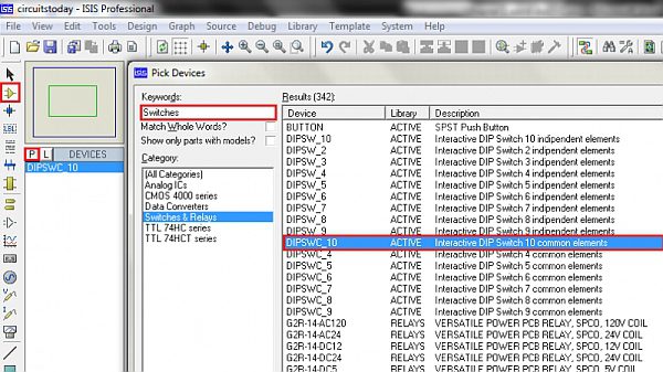
Step 4: Also select 10 Way common element DIP switch under switches category.
Step 5: Connect the circuit as per the circuit diagram and run the simulation
- How do I find LEDs in Proteus?
Open Pick devices (P), scroll to the Optoelectronics category or type LED in Keyword, and select an ACTIVE component. - How can I change LED forward voltage and current in Proteus?
Place the LED, right-click and choose Edit Properties (or double-click) and modify Voltage Drop and Forward Current. - What Model Type should I choose for an LED driven by a microcontroller?
Set Model Type to Digital when the LED is driven by a digital IC or a microcontroller. - How do I calculate the series resistor for an LED?
Use Rs = (Vsource – Voltage drop of LED) / Maximum Forward Current. - Can I change resistor values if the exact value is not in the library?
Yes, select a different resistor and adjust its resistance in the Edit Properties tab. - Where are bar graph displays found in Proteus?
Bar graph displays are under the Optoelectronics library; search by typing Bar graph in Pick devices. - How do I enable interactive simulation for LEDs?
Choose components with the ACTIVE property in the library search results for interactive simulation. - Does the software consider resistor wattage during simulation?
No, resistor wattage is not a concern during simulation unless planning a PCB design.