Summary of Perfboard Hackduino Arduino-compatible circuit
This tutorial outlines building a custom, low-cost (~$8) Arduino-compatible circuit on a perfboard for permanent embedding. It eliminates the need to reuse expensive $30 boards by soldering essential components directly onto the board. The guide covers gathering parts like an ATMega chip, voltage regulator, and capacitors, then details the assembly process including IC socket installation and wiring the LM7805 voltage regulator.
Parts used in the Hackduino Project:
- 28-pin DIP IC Socket
- 16MHz crystal
- Momentary push-button switch
- 1k ohm resistor
- LM7805 5v voltage regulator
- 2 x 22pF capacitors
- 10nF capacitor (ceramic disc code '103')
- 22uF capacitor
- ATMega168 or 328 microcontroller chip with Arduino bootloader
- Breadboard style perf board
This tutorial will go through the steps involved in fabricating your own Arduino-compatible circuit using just ~$8 of parts (this includes the ATMega chip!). This is perfect for installing and embedding in permanent pieces, as you don’t need to waste a full $30 Arduino board in a project you will never need to reprogram or touch ever again. It is also great because you can solder anycustom circuits (LEDs, other ICs, any external analog circuit) on the same board, and customize in terms of shape and size.
I assume you have a regular Arduino board already, so pulling out the chip to reprogram it shouldn’t be a big deal, since we’re going for minimal parts here. You could even go simpler by leaving out the reset button! To better illustrate the process, I did all the wiring on top of the board for tutorial purposes, but feel free to save yourself some space and make some of the connections on the copper-clad side of the board, as seen on hackduino.org or similar.
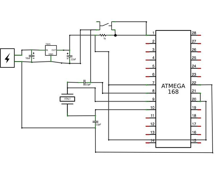
 Hackduino3_schem.pdf(595×842) 219 KB
 Hackduino3.fz540 KB
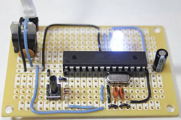
Step 1: Gather Components and Tools
Parts list and buy links:
• 28-pin DIP IC Socket – $0.30 – buy mouser
• 16MHz crystal – $0.55 – buy mouser
• momentary push-button switch – $0.15 – buy mouser
• 1k ohm resistor – $0.05 – buy mouser
• LM7805 5v voltage regulator – $0.35 – buy mouser
• 2 x 22pF capacitors – $0.12 – buy mouser
• 10nF capacitor (ceramic disc code ‘103’) – $0.10 – buy mouser
• 22uF capacitor – $0.02 – buy mouser
• ATMega168 or 328 microcontroller chip w/Arduino bootloader (you can use the one on your Arduino for now!) – $4.00-$5.50 – buy unbootloaded mouser(cheaper) / buy bootloaded sparkfun(expensive)
• breadboard style perf board – $1.45 from electronix express (elexp), or $1.99 – from radioshack
Total cost of components: $7.39 (!!!) *22AWG wire is not included
I have created a Mouser project that includes everything you will need, except for the perfboard itself (Mouser doesn’t carry a good one at a good price). Also, this is the blank ATMega328 – so you will need to bootload the chip yourself. Also keep in mind that ordering in multiples makes everything cheaper! Here is the Mouser project.
Tools:
• IC Extraction Tool (you can use a min-flat head screwdriver to pop out chips as well) – buy
• Wire strippers
• Snips
• Multimeter
• Soldering Iron + solder
Step 2: IC Socket
First step is to figure out what exactly what you are putting into this circuit. For this tutorial all we will build, other than the ATMega necessities, is a voltage regulator, so I am leaving space at the top of the board for this. I also recommend leaving some space towards the bottom for a capacitor. However, if you know this will include much more than just the ATMega circuit, you should plan this out on your board now, and install the IC socket appropriately.
Most IC’s (Integrated Circuits), and consequently their corresponding sockets, have a notch on one end. In this photo, you’ll see the notch is towards the top of the board. This is extremely important to pay attention to both while building the circuit and when inserting the chip during the last step.
Go ahead and solder all 28 pins in, making sure the pins are sticking out of the copper side of the board.
Step 3: Voltage Regulator
LM7805 circuit goes next. The 7805 allows you to power the circuit with a 9v battery or even 12v DC power supply, and ouputs 5v which is what our chip wants. With the “chair” facing you, solder the 10nF capacitor connecting the right two legs of the 7805. In this position, from left to right, the pins are input voltage – ground – output voltage (5v).
10nF cap (labeled 103) bridges the GND and OUTPUT voltage.
For more detail: Perfboard Hackduino Arduino-compatible circuit
- What is the total cost of components for this project?
The total cost of components is approximately $7.39. - Can I use an existing Arduino board's chip for this project?
Yes, you can pull the chip from your regular Arduino board to reprogram it for this circuit. - How do you identify the correct orientation for the IC socket?
Most ICs have a notch on one end, which should be positioned towards the top of the board. - What voltage input does the LM7805 regulator accept?
The 7805 allows powering the circuit with a 9v battery or even a 12v DC power supply. - Does the article recommend leaving space for extra components?
Yes, it recommends leaving space at the top for the voltage regulator and at the bottom for a capacitor. - What tools are required to extract chips if not using an extraction tool?
You can use a min-flat head screwdriver to pop out chips as an alternative. - Is the 22AWG wire included in the component cost?
No, the text states that 22AWG wire is not included in the $7.39 total. - What is the pin configuration order for the LM7805 when facing the chair?
From left to right, the pins are input voltage, ground, and output voltage (5v).