
Summary of A solar tracking automatic motorized window blind retrofit using Arduino
This article details a DIY project to retrofit manual roller shades into an automatic motorized system using Arduino. The device adjusts shade position based on sun location and light levels to maximize daylighting while minimizing glare. By integrating a stepper motor with a digital luminosity sensor, the system automates shade control, addressing issues caused by human inactivity. The project emphasizes cost-effectiveness by utilizing existing shades rather than purchasing new ones.
Parts used in the Automatic Motorized Roller Shade:
- Arduino Uno
- Adafruit motor shield
- Headers
- Digital Luminosity Sensor
- Stepper motor with planetary gear box
- 12V Power supply
- 3D printed gear
- Elastic Band
- Soldering iron
- Clamps
- Spare wood/platform
- Wires for prototyping
- Electronic breadboard
- Ruler
- Digital Calipers
Buildings account for 20-40% of total energy use in developed countries. Window shades (or blinds) can help to reduce building energy use and improve visual comfort (i.e., reducing glare and increasing daylighting). A recent study showed that occupants are fairly inactive when operating manual roller shades (O’Brien et al. 2013) which could lead to increased visual discomfort and increased heating and cooling energy use. With aspirations to address issues associated with human inactivity I created an automatic motorized roller shade.
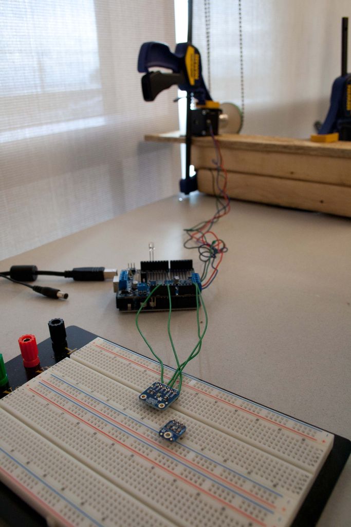
The motor moves the shade position depending on the of the location of the sun and the illuminance (i.e., amount of light) hitting a workplane (e.g., your office desk or kitchen table).
One of the best parts of this instructable is that you do not need to purchase a brand new roller shade to make this work. I will demonstrate how to retrofit an existing manual roller shade into an automatic motorized one using Arduino. The project used Arduino with the Adafruit motor shield to control the interaction between a stepper motor and a digital luminosity sensor.
This Instructable is structured:
- Introduction: What is ‘good’ shade position?
- Required supplies
- Assembly
- Code explanation
- Summary
Step 1: What is ‘good’ shade position?
As the sun moves across the sky during the day, where should the shade be positioned? What if it is a very sunny day and there is too much light entering a space causing glare? What if it is an overcast day? This step tries to answer these questions by asking: What is ‘good’ shade position?
In general, we want the shade position to let in as much light as possible without cause any visual discomfort (i.e., maximize daylighting and minimize glare).
The picture above was taken sitting down at my office desk. It was an example of ‘good’ shade position because the shade was positioned so it was blocking direct sunlight yet was still allowing maximum diffuse sunlight to enter into my workspace.
Sunlight can be broken into essentially two components: direct and diffuse. The direct component comes straight from the sun whereas the diffuse component is created when a portion of direct sunlight scatters due to molecules in the atmosphere.
This project aims to control shade position to always block direct sunlight when present and maximize the diffuse component entering the workspace.
Step 2: List of Supplies
Arduino Hardware:
- Arduino Uno (http://www.arduino.cc/)
- Adafruit motor shield (http://www.adafruit.com/products/1438) $19.95
- Headers (http://www.adafruit.com/products/85) $1.95
- Digital Luminosity Sensor (http://www.adafruit.com/products/439) $5.95
Stepper Motor:
- Stepper motor with planetary gear box $33.95 (http://www.omc-stepperonline.com/nema-17-stepper-m…)
- Power supply – 12V (May be required if motor cannot produce enough torque through a USB port)
Some notes on the stepper motor. You do not need to use this stepper motor and it may be possible to find a cheaper one. But you must consider torque and speed. This stepper motor easily produced enough torque to raise and lower the shade. It moved at a slow, yet smooth (stepping angle of 0.067°), speed because it had a gearbox. You can control the speed of the stepper motor via the code provided but up to a certain point; however, this could create discontinuous motion which could potentially cause the ball chain to skip some gears. High torque and low speed motors work well for this project.
3D printed gear:
- 3D printed gear via Shapeways.com ~$15-30 (Discussed in step 2)
- Elastic Band (The thick ones found when buying broccoli work great)
Lets discuss the design of the ball chain gear. I searched online to see if I could just the gear that comes with a generic roller shade but I could not find one anywhere. It seems to get one you must buy an entire roller shade.
Luckily John Abella created a parametric CAD file of a ball chain gear. The file should be opened with OpenSCAD software.
Parametric 3D ball chain gear CAD file by John Abella: http://www.thingiverse.com/thing:12403/#files
OpenSCAD software: http://www.thingiverse.com/thing:12403/#files
The parametric file requires the following inputs that you should measure with digital callipers in mm:
- Motor shaft diameter
- Ball diameter
- Ball count (This is one of the inputs to determine gear radius)
- Ball spacing
- Link diameter
John Abella has also added code so that different shaft options can be used. The code outputs total height and diameter. Shapeways has limits to the size of the printed piece. I used shaft type #3 to match the stepper motor shaft. I designed the flat spot diameter so that force fit was required to fit the gear onto the shaft. It was difficult to fit the ball chain to the gear correctly even with precise measurements using a calliper. I suggest making the gear diameter large so that you maximize the number of grooves in contact with the ball chain.
Attaching a rubber band around the gear increased friction between the ball chain and gear. This should help reduce slippage. Once you are happy with the design ‘compile and render’ the file to type .stl and upload it to shapeways.com or use your own 3D printer for manufacturing. I used the default white nylon material – Strong & Flexible.
Tools for assembly:
- Soldering iron (To assemble Adafruit motor shield)
- Clamps (I used quick release clamps)
- Spare wood/platform
- Wires for prototyping
- Electronic breadboard
- Ruler
- Digital Calipers
For more detail: A solar tracking automatic motorized window blind retrofit using Arduino
- How does the motor move the shade?
The motor moves the shade position depending on the location of the sun and the illuminance hitting a workplane. - Can I retrofit an existing manual roller shade?
Yes, you do not need to purchase a brand new roller shade; you can retrofit an existing manual one into an automatic motorized one. - What is the goal for good shade position?
The goal is to let in as much light as possible without causing visual discomfort by blocking direct sunlight while maximizing diffuse sunlight. - Does the stepper motor require specific torque?
Yes, high torque and low speed motors work well, and the chosen motor must produce enough torque to raise and lower the shade. - What software is needed to design the 3D printed gear?
You must use OpenSCAD software to open the parametric CAD file of the ball chain gear. - How can you reduce slippage between the ball chain and gear?
Attaching a rubber band around the gear increases friction between the ball chain and gear to help reduce slippage. - What inputs are required to generate the 3D gear file?
The file requires measurements for motor shaft diameter, ball diameter, ball count, ball spacing, and link diameter. - What material was used for the 3D printed gear?
The default white nylon material Strong & Flexible was used for the printed piece.
