Many fun environmental sensors need a hardware interrupt. With the MKR1000, you no longer need to choose! You get I2C, analog ins too!
Things used in this project
Hardware components | ||||||
 |
| × | 1 | |||
| × | 1 | ||||
| × | 1 | ||||
 |
| × | 1 | |||
 |
| × | 1 | |||
| × | 1 | ||||
| × | 1 | ||||
 |
| × | 1 | |||
| × | 1 | ||||
 |
| × | 1 | |||
 |
| × | 1 | |||
Story
I love watching the weather, and I wanted to try to capture and graph it. Home weather stations let me see the details for “now”, and sometimes tallies for the past hour, or day. I wanted to do more, and use an Arduino for the job. Everyone starts with Temperature and Humidity, sometimes Barometric Pressure, but I wanted more! Wind speed and rain measurement each wanted hardware inputs. Once I’d mastered using i2c, I found things like the AS3935 Lightning Detector! And then the sadness set in… I didn’t have enough hardware interrupts to do the job with your basic Arduino. Sparkfun even has a weather sensor board for the Photon, but it’s still limited. I’d have to choose, and do without some of the sensors. 🙁
Then I saw the MKR1000, and I spotted the BEST FEATURE, it has 8 hardware interrupts! Now I could have it all!
Choosing your Sensors
Sensors come in three basic flavors;
- Analog: light (including IR and UV), wind direction, gases, load cells…
- I2C: temp, humidity, baro pressure, accelerometer, gyro…
- Interrupts: rain tippers, wind speed, lightning, timers…(Features like serial, PWM, clocks, servos use timing interrupts)
The MKR1000 has plenty of I/O for all of these!
NOTE WHICH VOLTAGE YOU NEED FOR YOUR I/O on I2C and Interrupts! For example, the MKR1000, the Photon, and many flavors of Arduino use 3.3v I/O instead of 5v. If your CPU and the sensor(s) that you want use different voltages, you will also need to use level-shifters between those devices.
All of the sensors that I’ve been using are common enough, available from Adafruit, SparkFun, Element-14 and others, and usually cost between $5-10(US). Gas sensors usually cost $10-$20. For the lightning detector (AS3935 chip), I chose the Embedded Adventures MOD-1016, which is $26 (US) to get the antenna on the board as well. I also bought the Sparkfun Photon Weather Shield, since I have a Photon, and I’ll probably buy their “weather meters” (wind speed and direction instruments). Maybe I’ll add a Soil Moisture sensor, once I figure out where I’ll be mounting the MKR1000. Some sensors do not like having long leads.
Assign your Sensors to Pins
Once you know which sensors you want, you’ll know which type of inputs you will need, the next step is to decide which sensors will go on which pins. I start on paper, but I’ll also add this list as a block comment in my code, as a reminder.
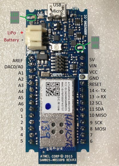
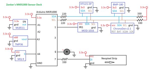
Here are the MKR1000 pin assignments that I’ve made for my sensor deck.
- A0 (I’m saving A0 in case I need the DAC later…)
- A1 ML8511 UV sensor
- A2 visible light sensor
- A3 TMP36 local temp sensor
- A4 MQ-9 gas sensor
- A5 moisture sensor
- A6 wind speed sensor?
- 0 (HW INT) pushbutton
- 1 (HW INT) AS Lightning Detector
- 2 (HW INT) wind speed anemometer (interrupt per rotation)
- 3 (HW INT) Rain Tipper…
- 4
- 5
- 6 (shared with on-board LED)
- 7 NeoPixel output…
Getting Started…
For the beginners among you, I suggest starting with each sensor you are going to use, one at a time, and start by loading the example code, and installing the needed libraries. Remember to change the sensor pin, to match the pin assignment of your choice, and save a copy of the demo code in your project folder.
When you can run the test code, and read the results from the Serial Monitor, you are ready to try adding another. And when you are done testing each sensor, they are now all wired and ready to start building your larger sketch!
My original tinkering with the sensors included using an i2c-based Reat-Time Clock (RTC), so I could log to an SD memory card. Although the MKR1000 has it’s own RTC, and a battery, I haven’t been able to get the clock to keep time with only the battery, so I’ll be keeping the ChronoDot v2.1 i2c RTC as well.
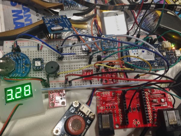
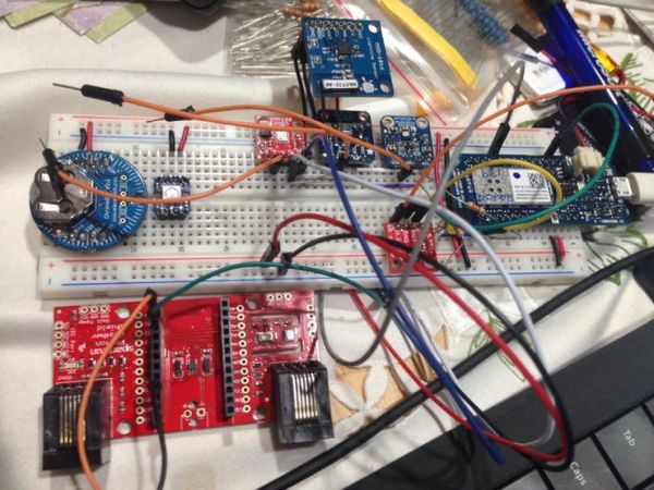
Looking at the breadboard in my image below, you can see the various jumpers in use. The orange are for the 3.3v power to each sensor, so I can only plug them in when I’m ready to work with them. (It’s easy to disable a
sensor by unplugging the orange jumper.)
A Note about Libraries
I’ve found that some of the libraries that you can install, do NOT work perfectly with the MKR1000, and/or with Arduino.cc IDE version 1.6.7, and you may need to do some tuning, depending on how old your sensor is. One example of this is the older ATOMIC_* macros in the older AVR libc library (they were dropped in Arduino IDE 1.6.5), and there is a great thread about problems and suggested solutions in a forum thread on Arduino.cc. Making some of the suggested changes are something for an intermediate Arduino hacker, but will probably be intimidating for newer hackers. And, for slightly older libraries, the original author may not be around to update the library and eliminate the dependency.
Unfortunately, you usually won’t be able to know which libraries need to be tuned before you buy your sensors and test them. At that point, I recommend that you look at the error messages that appear in orange when you try to upload your sketch carefully, to see if the problem is in your code, or in a library, before you start changing your code. If it’s in the library, do a web search for “arduino” and the error message. If you can’t find a solution, try to email the author, and let them know about the error, and maybe they will update the library.
I’ve bought individual chips, trying to save money. I’ve decided that, until I’m ready and able to make my own circuit boards (probably using EagleCAD and OSHPark), it’s easier to buy sensor modules from Adafruit and SparkFun, since they are great about keeping their libraries patched.
A Bit about WiFi and Encryption
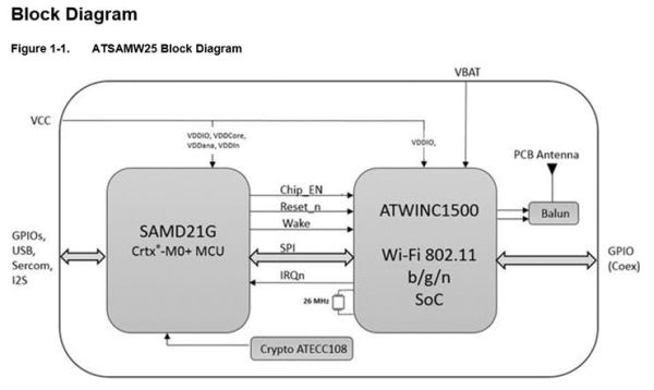
I also thought about the wifi for making my weather sensors report in to a website. We even have an encryption engine on the MKR1000, to help keep our data safe in transit over the Internet! But, that’s more than I will be able to do in this first project. It’s on my list to do, because making data security part of your design is important for the Internet of Things, but I am running out of time for adding my entry for the MKR1000 contest. Watch for my “version 2” of this project. Here is a block diagram of the SAMD module that is the heart of your board.
I can offer you one tip to get started with the on-board WiFi: Make sure that you are using the most current version of the WiFi101 library! If you do not, your sketch won’t recognize the wifi module, and your wifi sketches will only report that if there is error checking on the calls to the wifi module.) I need to thank Charif Mahmoudi for pointing that out in his great “Getting Started with MKR1000” tutorial here on Hackster! At the time of my hacking, you could find the WiFi101 Githuib here.
Tips for Analog Sensors
Most “analog output” sensor modules will produce a simple analog voltage output, and this is easily read using the analogRead of the sensor pin. But, then you need to know what that means. Normally, you will need to use the map command, or you may need to perform a bit of math. Resistive elements will usually need some extra circuitry. You may want to add a potentiometer to “fine-tune” the voltage.
In other cases, you’ll need equations to turn the output voltage into something that humans will understand. The TMP36 temperature sensor is one well-documented example of this. This part was designed to read out in degrees Celsius, so you need to measure the voltage, and do some math to get C, and if you want Fahrenheit, you’ll need to convert C to F. Reading the data sheets of components will explain how the part works, but you will find it easier to follow in someone else’s footsteps as you build up your experience.
Yet other sensors need an amplifier, in order to make the tiny voltage swings large enough for your ADC to get a good range from high to low. These types of sensors (load cells, moisture, accelerometer) are where I find it best to spend some money, and buy a module that already has an amp, and a library to help understand the range of the output.
Tips for Using I2C Devices
I2C is sometimes called a “two-wire interface”, because you need a clock signal, as well as a data signal. (You only need one data wire, because the “master” and the “slave(s)” will take turns sending data on it.) Of course, your I2C sensors will also need a ground and a power lead as well, and that ground lead needs to be tied back to your CPU.
Every I2C device will have a hexidecimal address on the bus. It’s best to avoid using multiple devices with the same address. (If you want to have multiples, you need to manage them with extra circuitry, in order to “enable” the one you want to communicate with, and then disable it when you are done, before you enable another for communication.) The documentation should tell you which address(es) a device can be. (NOTE: If you have two devices on the I2C bus with the same address, and both have an “Enable” or “Shutdown” pin, you will be able to disable one while the other is awake. However, you cannot just turn off power to the vdd pin, since the sensors can pick up some power from the SDA and SCL pins, and will result in bad readings for that address. The error-checking for I2C is not good enough to detect/correct for this case.)
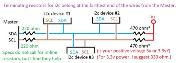
The I2C specifications tell us that we should have a “strong” pull-up resistoron both the clock and the data leads, on the sensor that is farthest on the wire. Because of this, some sensor modules already have resistors on-board, and you may just need to add a couple jumpers, so be sure to read the documentation for the module(s).
In addition to the “bus terminating resistors”, I have also found a hint from one hacker long ago, to add a resistor in-line both the data (SDA) and clock (SCL) leads. This greatly improved the reliability of data readings from a couple of sensors. With the MKR1000, using 3.3v signaling, I’m using 220 ohm resistors. On a 5-v CPU, you may want to try 330 ohm. See the schematic below to see the difference in the placements.
What will you do with the data?
Right now, I’m just sending it to the Serial Monitor. You could add an LCD. I was going to add an SD card, but now that I have wifi built-in, I want to upload the data to a cloud… imagine having a few of these sensor decks around, knowing their latitude and longitude, and being able to triangulate a lightning strike by comparing the power readings from each station for a given lightning strike!
ASIDE: 2017-11-29; I haven’t been able to get the hardware interrupts working on the MKR1000. I’m making notes and sensor experiments for a Grade 9 class (age 13-14), and maybe you will find the sketches interesting. The class is built around the Adalogger M0 board, and saves the data to an SD card, and there are still plenty of pins for a WiFi module.http://arduinoclass.pbworks.com
While I’ve been working on the sensors, I also spotted the SODERSVIK lamp fixture at IKEA (See the image below.). Imagine replacing the white LEDs inside this lamp with 20 Neopixels, and adding an IR remote receiver. Blowing wind could look like clouds rolling by, and the color could indicate the temperature. The remote could also chose to momentarily show some other information, like the temperature change during the past 12 hours.

What do you want to monitor and display?
Schematics
Sensor Deck schematic
Code
//Takes an average of readings on a given pin
//Returns the average
int averageAnalogRead(int pinToRead)
{
  byte numberOfReadings = 8;
  unsigned int runningValue = 0;

  for(int x = 0 ; x < numberOfReadings ; x++)
    runningValue += analogRead(pinToRead);
  runningValue /= numberOfReadings;

  return(runningValue);
}
I2C bus scanner
Arduino
// --------------------------------------
// i2c_scanner
//
//   Found at http://playground.arduino.cc/Main/I2cScanner?action=sourceblock&num=1
//     26 OCT 2015
//
// Version 1
//    This program (or code that looks like it)
//    can be found in many places.
//    For example on the Arduino.cc forum.
//    The original author is not know.
// Version 2, Juni 2012, Using Arduino 1.0.1
//     Adapted to be as simple as possible by Arduino.cc user Krodal
// Version 3, Feb 26  2013
//    V3 by louarnold
// Version 4, March 3, 2013, Using Arduino 1.0.3
//    by Arduino.cc user Krodal.
//    Changes by louarnold removed.
//    Scanning addresses changed from 0...127 to 1...119,
//    according to the i2c scanner by Nick Gammon
//    http://www.gammon.com.au/forum/?id=10896
// Version 5, March 28, 2013
//    As version 4, but address scans now to 127.
//    A sensor seems to use address 120.
//
// This sketch tests the standard 7-bit addresses
// Devices with higher bit address might not be seen properly.
//
// Zonker Harris added device descriptions, comments.  OCT 10 2015
//

#include <Wire.h>

void setup()
{
  Wire.begin();

  Serial.begin(9600);
  Serial.println("\nI2C Scanner");
}

void loop()
{
  byte error, address;
  int nDevices;

  Serial.println("Scanning...");

  nDevices = 0;
  for(address = 1; address < 127; address++ )
  {
    // The i2c_scanner uses the return value of
    // the Write.endTransmisstion to see if
    // a device did acknowledge to the address.
    Wire.beginTransmission(address);
    error = Wire.endTransmission();

    if (error == 0)
    {
      Serial.print("I2C device found at address 0x");
      if (address<16)
        Serial.print("0");
      Serial.print(address,HEX);
      // Serial.print(address);  If needed, print the address in decimal
      //
      // Now, detail sensors that we know about or expect...
      if (address == 3)
      {
        // DEC 3 = 0x03 HEX = AS3935 Lightning Sensor
        Serial.print(" - AS3935 Lightning Sensor");
      }
      if (address == 64)
      {
        // DEC 64 = 0x40 HEX = HTU21D  Humidity and Temp Sensor
        Serial.print(" - HTU21D Humidity and Temp Sensor");
      }
      if (address == 104)
      {
        // DEC 104 = 0x68 HEX = DS1307 (Chrono-Dot?) RTC
        Serial.print(" - DS1307 RTC (Chrono-Dot?)");
      }
      if (address == 119)
      {
        // DEC 119 = 0x77 HEX = BMP180 Barometric Pressure and Tem Sensor
        Serial.print(" - BMP180 Barometric Pressure and Tem Sensor");
      }
      Serial.println(" ");

      nDevices++;
    }
    else if (error==4)
    {
      Serial.print("Unknow error at address 0x");
      if (address<16)
        Serial.print("0");
      Serial.println(address,HEX);
            if (address == 3)
      {
        // DEC 3 = 0x03 HEX = AS3935 Lightning Sensor
        Serial.print(" - AS3935 Lightning Sensor");
      }
      if (address == 64)
      {
        // DEC 64 = 0x40 HEX = HTU21D  Humidity and Temp Sensor
        Serial.print(" - HTU21D Humidity and Temp Sensor");
      }
      if (address == 104)
      {
        // DEC 104 = 0x68 HEX = DS1307 (Chrono-Dot?) RTC
        Serial.print(" - DS1307 RTC (Chrono-Dot?)");
      }
      if (address == 119)
      {
        // DEC 119 = 0x77 HEX = BMP180 Barometric Pressure and Tem Sensor
        Serial.print(" - BMP180 Barometric Pressure and Tem Sensor");
      }
    }
  }
  if (nDevices == 0)
    Serial.println("No I2C devices found\n");
  else
    Serial.println("done\n");

  delay(5000);           // wait 5 seconds for next scan
}

/*  The output looks like this...
 *
 * Scanning...
 * I2C device found at address 0x03 - AS3935 Lightning Sensor
 * I2C device found at address 0x40 - HTU21D Humidity and Temp Sensor
 * I2C device found at address 0x68 - DS1307 RTC (Chrono-Dot?)
 * I2C device found at address 0x77 - BMP180 Barometric Pressure and Tem Sensor
 * done
 *
 */