This is my first time designing a PCB for MSP430. I really like the NRF24L01+ booster pack but I would like something smaller to use for remote temperature sensors. With that in mind I’ve designed a 24.5 x 50 mm PCB (2 on a 5×5 cm prototype) featuring MSP430G2553 and an adapter for a 8-pin NRF24L01+ module using essentially the same pinout, with the intention of using the Spirilis library. There’s a jack socket to connect a 1-wire sensor (e.g. DS18B20), a 4-pin header to connect a temperature/humidity sensor (SHT22 or similar), a programming header that gives serial access, and 3 other general purpose I/O pins. You could connect a thermistor or LM35 to the jack socket by leaving off the 4.7K pullup resistor on the data pin. Power can be supplied by a CR2032 coin cell or via a mini USB and LDO voltage regulator.
Based on boosterpack design by Spirilis / 43oh. J.P.Norair’s suggestion to control TX/RX leds in firmware rather than hardware. Active low configuration avoids need for pullup resistors and transistors.
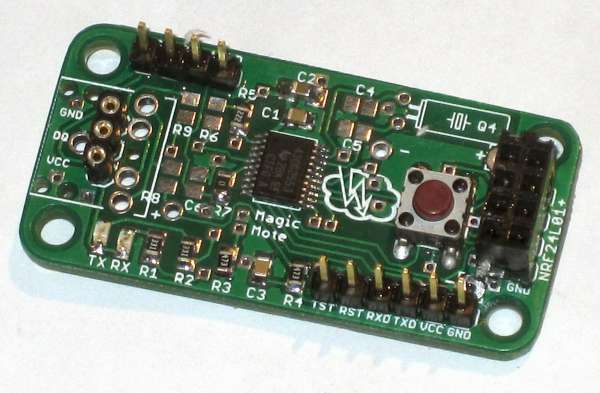
The PCBs arrived from Elecrow a couple of days ago and I populated the first one. This may be the first time I have successfully soldered a TSSOP.
This one is configured with a 3-pin SIP header for a 1-wire sensor instead of a 3.5mm jack socket. The 4 pin header will be used for output, so I left off R6 and C6 and substituted 0 ohms for R7.
I went backwards and forwards over the orientation of the NRF24L01+ header and eventually decided to leave it so that with a 2×4 female pin header the radio module would extend back over the board. This allows for greater compactness but renders the push button inaccessible. One way around that is to use a right angle female header. Another way is to solder the push button on the back (an advantage of using a through hole button) so long as the battery pack pack is not in the way.
Read more: Magic Mote MSP430G2553 wireless sensor node with NRF24L01+ module