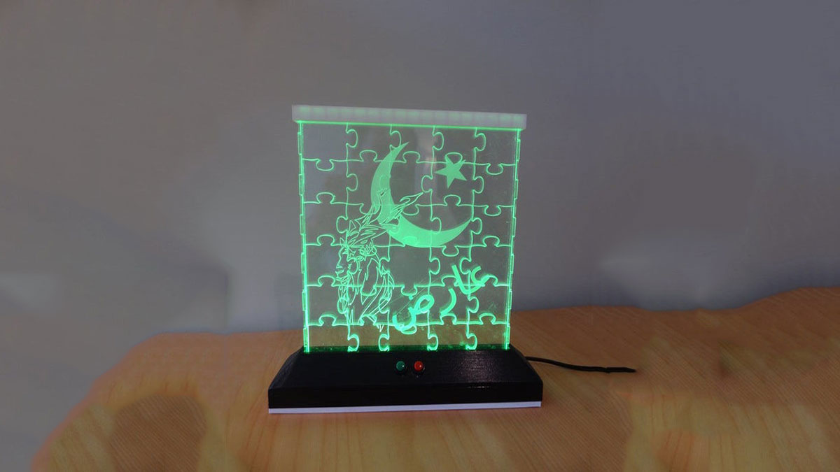
I have always enjoyed the various acrylic laser-cut night lights that others have made. Thinking more about these I thought that it would be great if the night light could also double as a form of entertainment. With this is mind I decided to create jigsaw puzzle that would fit into a thin box that would then be illuminated by an LED strip.
Regarding the actual lighting, I wanted the LEDs to slowly cycle through a range of colours with the user having the ability to either pause at a particular colour or skip through to a new colour.
Materials use:
- Two different colours of 3D printing filament
- Spray paint
- Sandpaper
- 2mm Acrylic (for creating the box)
- 6mm Acrylic (for creating the puzzle)
- Screws: M3 10mm
- Capacitor: 1000μf 6.3v
- Round, mini reset button (one red and one green)
- Rocker switch
- RBG LED Strip
- Arduino Nano V3
- Power barrel connector
- Step down transformer
- 12V power supply
Tools:
- Soldering Iron
- Multimeter
- CO2 Laser cutter
- 3D Printer
- Glue gun
- Acrylic cement
- Wire strippers
- Iron file
- Drill
- Drill bits (used to clean out holes in 3D printed model)
Software:
- Inkscape
- LibreCAD
- FreeCAD
Step 1: Preparing the Puzzel Art Work
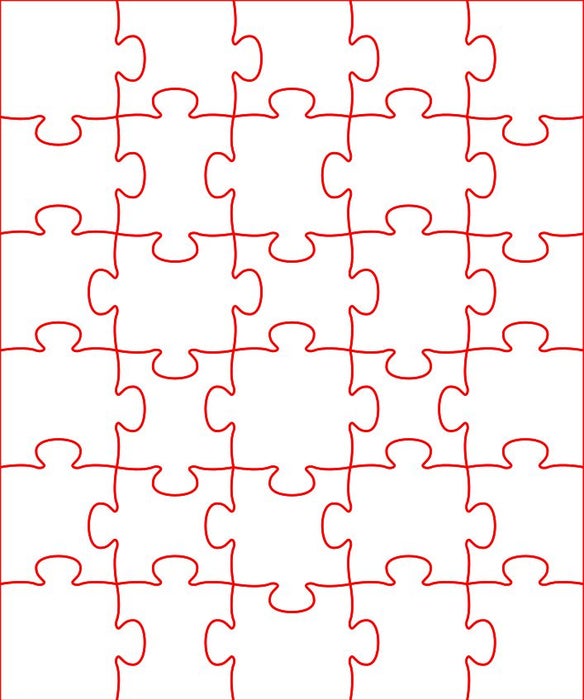
Since was cut using a CO2 laser cutter, the final file needed to be an SVG file.
Using Wolfie’s SVG Puzzle Generator, I created the basic puzzle map.
My puzzle was created for a friend of mine’s son. The family is from Pakistan and so I wished the lamp to have a Pakistani flavour. I therefore chose to create a puzzle using the name of his son, the Pakistani flag and the Markhor (national animal of Pakistan). I also initially intended to print the lamp base in green but unfortunately ran out of green filament.
Using the trace options in Inkscape I converted the required PNGs to SVGs and added them to the puzzle map.
The colours were set so that the puzzle base was cut while the picture parts were etched.
Step 2: Making the Box
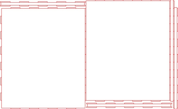
The case was designed using LibreCAD and then exported to a SVG file. This was then edited in Inkscape in order to set the correct colour and line thickness for cutting on the CO2 laser cutter.
Using acrylic cement the I stuck the sides of the box to only one of the large sides. The actually puzzle can therefore be built in the box. Once complete the second large size is placed over the top of the puzzle (slotting into the relevant slots) and held in place by the white top cover and the LED base.
Acrylic cement is not great to work with as it is easy to accidentally destroy your final finish by messing the acrylic on the main display parts of the box. Because of this I left the brown protective covering that comes with the acrylic on until the edges, which been cemented together, had dried. Having said this I did need to take care not to accidentally cement the protective layer in between the joins.
In short, at this point I had have a very shallow box that could hold the completed puzzle with one large loose piece of acrylic that could then be placed over the top, locking into the slots created by the sides of the box.
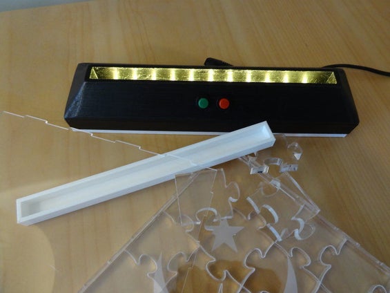
Step 3: Printing the Base and Top Cover
Using FreeCAD I designed and printed the attached pieces:
- Top cover (white)
- Base (back; in a perfect world this would have been green)
- Base cover (white)
For some reason the corners of the sloping sections of the base did not print very smoothly. Sanding them smooth resulted in a very uneven finish to the base. I therefore sanded the whole base down with fine sandpaper and then spray painted it back to achieve an even finish. In hindsight if I had printed it in white, I could have spray painted it the green colour that I initially wanted it to be.
I then stuck the RBG LED strip such that the LEDs faced up towards the base of the puzzle, feeding it back into the inside of the base via the slot provided. The sticky surface underneath the LED strip did not hold the strip down properly and so I added some super glue to secure it properly.
The reset buttons, rocket switch and power barrel connector where also inserted or screwed in. Some of the holes need to be drilled or filed out a little before these bits would fit properly.
Step 4: Programming the Arduino and Testing the Setup
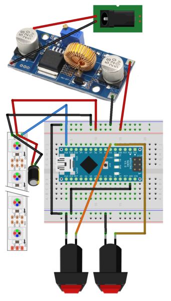
I then set up your bread board as shown above. Initially there was no need to include the transformer or barrel connector as the project was powered and programmed via the USB power, connected to my computer.
From the code you will see that the LEDs will cycle slowly from one colour range to the next. If button 3 (green) is pushed, the LEDs change to the next main colour in the sequence. If button 2 (red) is pushed then the LEDs stop changing and remain displaying the current colour. To continue seeing the colours change, the red button simply needs to be pushed again. Pausing the display does not pause the programme and so when the red button is pushed again, the LEDs will jump to the current colour that the programme is working through.
Next I needed to wire everything into the box as per the next step.
Source: LED Jigsaw Puzzle Light (Acrylic Laser Cut)