I am curious. I like to know how things work. For the curious, this Instructable will try to explain some of the Arduino electronics.
I suspect many people have built Arduino projects but couldn’t get them to work. I hope to provide some knowledge and skills to help fix hardware problems such as wiring errors and bad components.
After some Internet searching, I found an electronics tutorial that I like and trust:
http://www.ladyada.net/learn/arduino/index.html
“This tutorial is by Limor Fried”
In fact, I recommend it to all Arduino readers. There is some overlap of information but lots of multimedia and more on programming.
So who am I? I am a Lazy Old Geek (L.O.G.). I am not a degreed engineer but I’ve been around the electronics field for over 40 years starting as an electronics tech in the USAF. I spent many years testing electronic systems.
Arduino Basics:
As most of you know, Arduinos are based on a little black chip called a microcontroller. This is the heart and brains of the Arduino. You don’t have an Arduino without one. There are many flavors of the Arduino microcontroller but they all have the same functions. Currently the most popular for the DIYers is the ATmega328. See picture.
Microcontroller: A microcontroller is a CPU (central processing unit) with memory and interface circuitry built-in to the chip. Basically, the CPU takes all the commands in the program (sketch) (.PDE) and does what they tell it to do. Notice that I said what the commands tell it to do; I did not say what the programmer wants it to do. Writing a successful program is telling the CPU exactly what you want it do in the language it knows.
Frequently asked: Yes, the ATmega328 can always be used instead of the ATmega168 as the hardware is exactly the same. The ATmega168 may not replace the ATmega328 as it has less memory so bigger programs may not work.
Technobabble: The rest of this section is for Geeks only.
| Device | Flash | EEPROM | RAM |
| ATmega168PA | 16K Bytes | 512 Bytes | 1K Bytes |
| ATmega328P | 32K Bytes | 1 K Bytes | 2K Bytes |
What does this mean? The K stands for kilo, a multiplier which in this case, means multiply the number by 1024. Bytes are just a place to store information (data). This is basically the only difference between the two microcontrollers.
Flash: is a type of memory that holds program information, even after the Arduino is disconnected from power. The same program will run anytime power is reapplied to the Arduino. This is the same way USB flash drives and digital camera cards retain their information.
EEPROM: is memory that also retains information after power is shutoff. It is different from Flash as it can be written by the program instead of the program itself. The Arduino instructions to use EEPROM memory are EEPROM.read() and EEPROM.write().
Tip: Be sure to have:
#include //in your sketch(program). The limitation is, even in the ATmega328, there is only 1024 bytes so only so much data can be stored. Tip: By the way, I never got this to work. RAM: is also memory but it is volatile meaning it will go away when you turn off power. Sketches use it to store temporary information such as variables. What is a variable? Well, it is something that can change. Examples are the temperature or the time of day. Here is part of a sketch that converts a temperature sensor reading to degrees C (Centigrade) and degrees F (Farhenheit). float Vt=(float) sensorValue3Avg*5.0/1023.0;
float R=(5.0-Vt)*10.0/Vt;
float TinC=281.583*pow(1.0230,(1.0/R))*pow(R,-0.1227)-150.6614;
float TinF=TinC*(9.0/5.0)+32;
All of these float variables are stored in RAM and will be overwritten the next time a measurement is taken and are lost when power is turned off.
Basically, variables are just labels for locations in RAM. Float variables are a specific type of variable. With this label, the sketch knows where to go to store the value it wants or retrieve the value stored at that location. The specific type determines how much room is needed and how to interpret the information.
Besides the CPU, flash and RAM, the ATmegas have interface circuitry built in:
Serial interface: this allows the CPU to talk to the PC through a serial port or through USB and I believe it’s used to communicate over I2C. This is also how it talks to serial LCDs.
Analog to digital converter (ADC): This allows the ATmega to convert analog voltages to digital data (will be discussed in another Instructable).
PWM (pulse width modulation): circuitry to output ‘analog’ voltages
Timers: for timing events, most often used to set delays between program steps, e.g., blinking LEDs.
If you have ever looked at the datasheets on these ATmegas and understand them, then maybe you should be writing this instead of me.
Prefixes: There are a lot of letters attached to electronic terminology that may be confusing. E.g. 16mV, 10Kohms, 20uF. These letters are called prefixes (and suffixes) that are just multipliers to the value. E.g., 10Kohms is (10 times 1,000) ohms or 10,000 ohms. See the table below.
Non-essential Info: Unfortunately, if you’re talking computer memory 1Kbyte is 1024 bytes. This is because computer people like to make everything complicated. So to them K is 210. Megabyte can mean 1,000,000, 1,048,576 or 1,024,000. Don’t ask, check it out on Wikipedia.
Step 1: Basic Electronics
One of my earliest experiments in electricity was when I was about eight. I think we were studying electricity in Cub scouts. We were studying about voltages and loads and complete circuits. So I had a flash of brilliance (to bad it wasn’t a flashing warning light). I figured for a complete circuit all I needed was a wire so I took the two ends of the wire and plugged them into an AC outlet. Kaboom! I sure did have a flash of brilliance. In truth it was a complete circuit, however my dad didn’t see it that way. DO NOT TRY THIS ONE!
Now this is an unusual way to approach electronics but I think it will make it easier to understand, eventually.
Complete circuit: For anything to happen electrically, you have to have a complete circuit. This is a fundamental principle. A good example is a flashlight. The first drawing shows a complete circuit. A complete circuit consists of a power source (battery), a load (lamp) a connection from the power source to the load (white wire) and a connection from the load back to the power source (black wire). Electricity has a path from the voltage to the load and from the load back to the source making a complete circuit.
So why do I use this concept of complete circuits? I like it because you can focus on what you are concerned about and not worry about the rest of the circuitry. If you have a problem, say an LED isn’t blinking, then you can concentrate on the components that are needed to make that LED light up and not worry about everything else.
Some complete circuit examples in the Arduino world:
Power: One complete circuit could be a 6V battery connected to the Vcc pin of the ATmega(the load) and the ATmega ground pin connected back through the ground to the other side of the battery. See picture.
Okay, so there may be a few questions.
Some may ask: what does this picture mean. Well, this is a schematic and I will get into that in a minute.
Others will ask: how can you power an Atmega chip with 6V. Technically, this Atmega can be powered from 1.8Vdc to 6Vdc so this would work.
Others may ask: how can this be a complete circuit? It doesn’t do anything. It is true it doesn’t do anything but it is also a complete circuit. Who cares you may ask.
The answer is without this complete circuit, the Arduino will not work.
Schematic: A schematic is a pictorial representation of an electronic circuit. Remember that Atmega328 microcontroller, I showed you in the last step? Will I put the picture in this step also. See the little metal legs sticking out? Well, there are 14 of these pins on this side and 14 on the other. The pins are numbered from 1 to 28. On the left side of the chip, you can see a little half moon cutout. That means the pins under the white dot is 1 and they continue in sequence in a counter clockwise direction. The next picture shows a pictorial of the pins.
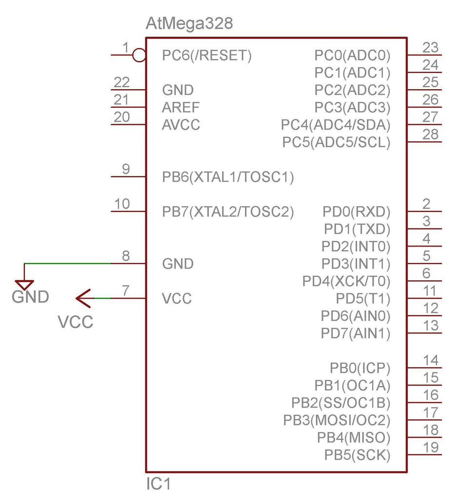
Back to the schematic. On the right side, you will see a rectangle with a lot of lines sticking out. This symbolizes the AtMega328. There are 28 lines and they are labeled 1 through 28.
So you may ask: why aren’t they labeled 1 thru 14 on the left and 28 thru 15 on the right, like in the pinout drawing? Well, some schematic symbols will do that. This one is setup more for functionality. The critical thing is what is connected to what pin number.
Technobabble: So what is that little circle on pin 1? Well, that means negative logic. Negative logic means that it happens when the signal is zero volts. Inside the box, it says /RESET. That means that the Atmega goes into reset when pin 1 is low (0V). The little slash (/) before the RESET means the same thing. You may also see a ‘RESET’ with a line over the top of it. That means the same thing. So whenever pin 1 is low, the AtMega is in RESET and cannot do anything.
So the little green lines on this schematic represent wires like the white and black wires of the battery-lamp complete circuit.
The symbol on the left is a battery cell. The side with the shorter line is negative and the longer is positive.
In summary: the complete circuit is the positive side of the battery connected to the VCC pin of the AtMega. The ground pin of the AtMega connected to the negative side of the battery.
For more detail: Arduino Electronics 101