Purpose and concept
The “LayoutLights” concept was born when I wanted to remotely control (using a PC with a USB port) the lights on the train layout.
I wanted to be able to switch on and off all the lights in buildings, structures and on platforms, streets and other locations.The basic principle is simple :
* one master controller has a USB interfact to the PC
* the master can control up to 15 slaves, with 4 outputs each, a total of 60 outputs
* the master remembers last saved situation in EEPROM so that at switch on, all is restored
* master and slaves communicate over a single wire (serial protocol in half duplex mode) on a TTL 5V level
* slaves each have 4 channels output which drive 4 darlington NPN transistord (BD139) so they can handle 4 x 1 A at 5..20 V* master chip = ATMEGA 328 PU
* slave chips = ATTiny 85The communication between PC and master :
* XXYYYY
—> XX = slave number ( 01 — 15)
—> YYYY = 4 bits one for each output (0000….1111)
* 20xxxx = synchronize EEPROM to current memory (save all)
* 30xxxx = get data from EEPROM to memory (restore all)
* 40xxxx = Set all outputs to current memory setting
* 99xxxx = RESET all EEPROM data to 0 (full system reset)Initializing the master memory :
* either run the system and enter a 990000 from the PC to reset all EEPROM to zero
* or upload the init script from the source before actually uploading the code in to the master controller
Schematics
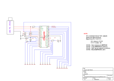
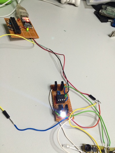
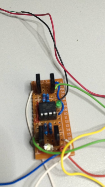
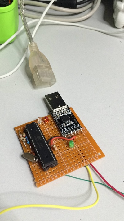
Physical build pictures
One Wire Serial Protocol
The One Wire serial protocol is quite simple… See below
Between cycles, the ports of both master and slave toggle between INPUT and OUTPUT mode accordingly.
The 200 mSEC cycle time is VERY long, extremely slow, but we want to make sure it works ok. Accuracy is more important than speed at this level.
X=50 mSec high signal,
__ = 5° mSec low signal
ACK = 150 mSec acknoledgement
db1..4 = 150 mSec status bit 1..4
chk = Timing Check 150 mSec pulse
MASTER : ______XXX_____db1_db2_db3_db4_chk_____
SLAVE : __________ACK_________________________ACK_
Source Files and code
![]()
| layoutlightmaster.dsn |
![]()
| layoutlightslave.dsn |
![]()
| layoutlightiniteeprom.ino |
![]()
| layout_light_master.ino |
![]()
| layout_light_slave.ino |