Summary of Joystick controlled Camera using Arduino
This article details a DIY project combining Arduino control with a joystick and LCD screen to manage two servos for camera pan-tilt movement. Built on a breadboard, the guide provides complete schematics, drawings, and code. The author notes that while the physical mount uses aluminum brackets, the electronics focus on integrating all components into one functional system using an Arduino Uno or Mega.
Parts used in Joystick controlled Camera using Arduino:
- Arduino uno / Mega
- Breadboard
- Jumper wires
- Joystick
- 20*4 LCD Display
- 2 servo's
- 10Kohm potentiometer
- NPN transistor (BC547B)
- 6 volt battery or power supply
Hi,
First of all, my English is not perfect =)
I’ve seen many projects with Arduino that describes how to control 2 servo’s with a joystick or use a lcd screen. All of the projects that i have seen are all seperate things. So i decided to make a short Instructable of these things combined. In this instructable is everything you need! Drawings, schematics, pictures and even the Complete Code that i’ve mostly written! This project is made on a breadboard because i just didn’t have the time to make this in a nice shining aluminum box :O
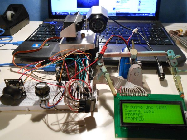
In the picture above you see the camera mounted in two aluminum brackets for the servo’s. I have a instructable for that too!!!
Check it out!
Link: http://www.instructables.com/id/Pan-Tilt-Servo-bracket-controlled-by-Arduino/
So…
Enjoy! =)
Step 1: Parts
Here is a list of all the parts you need.
- Arduino uno / Mega
- Breadboard
- jumper wires
- Joystick
- 20*4 LCD Display
- 2 servo’s
- 10Kohm potentiometer
- NPN transistor (BC547B)
- 6 volt battery or power supply
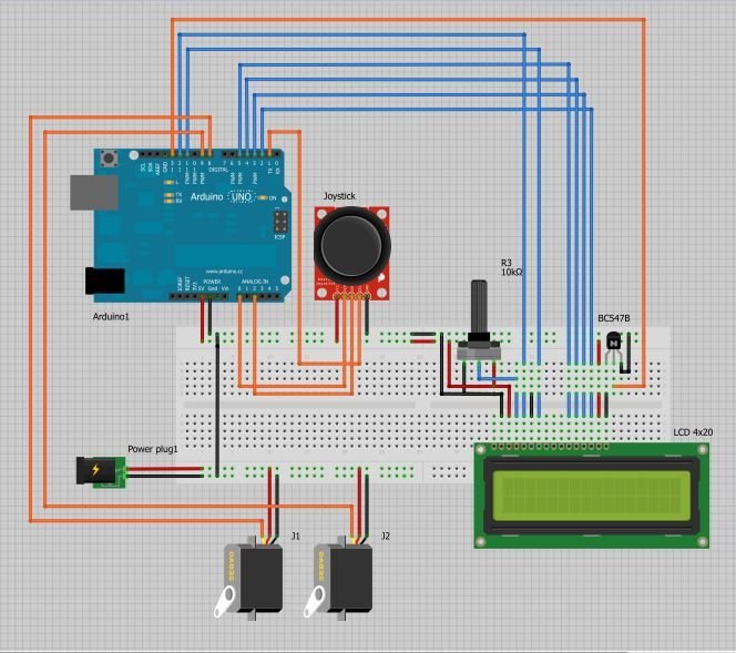
Step 2: Wiring
Hook up all the wires according to the picture.
I’ve made this circuit in Fritzing. It is very easy to use and even has multiple Arduino’s in it. Basic components are all there.
(I wanted to upload my own frtizing file but i could’nt succeed 🙁 )
You can download Fritzing here: http://fritzing.org/download/
Step 3: Code
Upload the code to the arduino and if everything is connected right the lcd screen will light up!
CODE:
#include <Servo.h>
#include <LiquidCrystal.h>

LiquidCrystal lcd(12,11,5,4,3,2);

const int servo1 = 9;       // first servo
const int servo2 = 8;       // second servo
const int joyH = 0;        // L/R Parallax Thumbstick
const int joyV = 1;        // U/D Parallax Thumbstick

int servoVal;           // variable to read the value from the analog pin

Servo myservo1;  // create servo object to control a servo
Servo myservo2;  // create servo object to control a servo
For more detail: Joystick controlled Camera using Arduino
- What components are required for this project?
The project requires an Arduino Uno or Mega, a breadboard, jumper wires, a joystick, a 20*4 LCD display, two servos, a 10Kohm potentiometer, an NPN transistor BC547B, and a 6 volt battery or power supply. - Can I use Fritzing to design the circuit?
Yes, the author created the circuit using Fritzing, which is described as easy to use and supports multiple Arduino models. - How do I know if the wiring is correct?
If everything is connected correctly after uploading the code, the LCD screen will light up. - Which pins are assigned to the servos in the code?
Servo 1 is assigned to pin 9 and Servo 2 is assigned to pin 8. - What libraries are included in the provided code?
The code includes the Servo.h and LiquidCrystal.h libraries. - Is a permanent enclosure required for this build?
No, the project was built on a breadboard because the author did not have time to construct a shiny aluminum box. - How are the joystick values read in the code?
The horizontal joystick value is read from analog pin 0 and the vertical value is read from analog pin 1. - Where can I find information about the camera bracket?
The author links to a separate instructable for a Pan-Tilt Servo bracket made of aluminum.