
Summary of Tears of Rainbow using an Arduino
The "Tears of Rainbow" project is an Arduino-based, modular light display featuring a VU BarGraph with peak indicators and triple-color LEDs. Designed for scalability and low cost, it uses chopped RGB LED strips mounted on tin plates to reduce soldering work. The system employs 74HC595 shift registers buffered by ULN2803 drivers to manage 72 PWM channels, allowing for dynamic color adjustment and brightness control while maintaining a giant, reconfigurable form factor.
Parts used in the Tears of Rainbow:
- Arduino
- RGB LED Strip (12V)
- Tin cookie plates
- 74HC595 Shift Registers
- ULN2803 Darlington Array
- Heat shrink tube
- Paper pads (1 cm)
- Tire-ups
- Prototype board
- Jumper wires
It’s time to release new updates for my first (ever) project with Arduino, “Color Light Music”. From artistic perspective, VU BarGraph style (IMHO) is the best one for spectral dynamic representation, and not much could be improved on this side. But this time, it cross my mind an another idea “Tears of Rainbow”. This blog about how successively (or awfully) the idea was brought to life. And of course, VU visual effects still there, updated with nice peak indicators, color adjustment flexibility (this time triple color LEDs), and PWM-ed brightness settings luxury. So, this is design requirements, I was following:
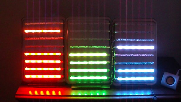
- make it as big as possible, GIGANTIC size !;
- Lego style, or many blocks / modules, which could be re-arranged in different pattern;
- extend-able, easy to add up more blocks later on;
- low price on hardware, no special display driver IC.
To simplify assembly work, I decided to buy RGB Led Strip. I had known, from my first project, that design would be composed with straight lines, and the longer lines means the more LED’s ( and consequently, soldering work). For comparison, one line on this display consist of 6 RGB leds, or 24 soldering connections. Using RGB strip, I reduce a workload 24 to 4, or 6 times. I envy to people, who have a patience to build 8x8x8 RGB led cube (or even 10^3 !). Addressable RGB strip would make life even easier, but I couldn’t find local re-seller, and was not going to wait shipment / customs. It’s summer time!
In order to easy reconfigure a style, for example, from 3 BarGraphs, needed in Color Music exposition, to just 1 GIGANTIC VU meter (*), RGB led strip is chopped-up and attached to 3 rectangular shape plates. I find out, that for some reason strip isn’t “sticky” enough, and to keep its perfectly align on a plate, I used a tire-ups at both ends. Luckily, it was quite easy to punch a holes in the plates for tire-ups just using kitchen knife.

It wouldn’t be so, if I use a glass as a back-plate
(I had such idea initially). Something to think, if you plan to work with a strip in your design. The same also true for wiring (32 wires per plate). Tin “cookie” plates just was made to be part of this project! And I even did not mention the heat dissipation, 1/3 of 5 meters strip consume around 12 W of power, it’s almost like my soldering iron!
One more things before I forget, I installed 1 cm paper pads to insulate contacts from the metal plate in the middle and on one side. Heat shrink tube takes care of the other end.
LED’s use 12V as power source, and as I need a lot of PWM channels to control their brightness , here comes 74HC595 buffered by ULN2803 at the outputs. Nothing special, 9 shift registers daisy chained to produce 72 PWM outputs. Two IC in a pair installed in reverse on a prototype board, to minimize a number of interconnections. As you can see from the picture, there is only 1! yellow jumper brought from pin 15 of the shift register to pin 8 of the Darlington array. Why they don’t make a shift register in DIP-16 package? There wouldn’t be any jumpers at all! Other alternative is using TPIC6B595.
Major Components in Project
Arduino
For more detail: Tears of Rainbow using an Arduino
-
What design requirements guided the project?
The creator aimed for a gigantic size, Lego-style modularity, easy extensibility, and low hardware costs without special display driver ICs. -
How did using an RGB strip simplify assembly?
Using the strip reduced soldering connections from 24 per line to just 4, cutting the workload sixfold compared to individual LEDs. -
Why were tin cookie plates chosen over glass?
Tin plates were selected because they allowed for easy punching of holes for tire-ups and provided necessary heat dissipation properties. -
How is the LED strip secured to the plates?
Tire-ups are installed at both ends of the strip to keep it perfectly aligned since the adhesive backing was not sticky enough. -
What power source do the LEDs use?
The LEDs operate on a 12V power source. -
How are the PWM outputs generated?
Nine 74HC595 shift registers daisy-chained and buffered by ULN2803 produce 72 PWM outputs. -
What measures were taken to insulate contacts?
1 cm paper pads were installed between the metal plate and contacts on one side, while heat shrink tube covered the other end. -
Why were two ICs installed in reverse on the prototype board?
This arrangement was used to minimize the number of interconnections required between components.
