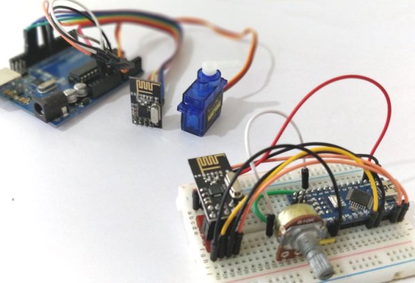
Summary of Interfacing nRF24L01 with Arduino: Controlling Servo Motor
This tutorial explains using nRF24L01 2.4GHz transceiver modules with Arduino to wirelessly transmit a potentiometer value from a Nano to control a servo on an Uno. It covers module features, wiring (SPI pins MOSI/MISO/SCK to 11/12/13, CE/CS to configurable pins 7/8), power notes, troubleshooting (power supply, fake modules, decoupling capacitors), required libraries, and provides transmitter and receiver Arduino code and operation details.
Parts used in the nRF24L01 Servo Control Project:
- Arduino Uno
- Arduino Nano
- nRF24L01 wireless transceiver modules (2)
- Servo motor
- Potentiometer
- USB cables for powering Arduinos
- Wires/jumper cables
- 3.3V power source (Arduino 3.3V or separate supply)
- Capacitors for decoupling (10uF and 0.1uF)
Arduino NRF24L01 Tutorial to Control Servo Motor
While Internet of things (IoT), Industry 4.0, Machine to Machine communication etc are getting increasingly popular the need for wireless communication has become incumbent, with more machines/devices to speak with one another on the cloud. Designers use many wireless communication systems like Bluetooth Low Energy (BLE 4.0), Zigbee, ESP43 Wi-Fi Modules, 433MHz RF Modules, Lora, nRF etc, and the selection of medium depends on the type of application it is being used in.
Among all, one popular wireless medium for local network communication is the nRF24L01. These modules operate on 2.4GHz (ISM band) with baud rate from 250Kbps to 2Mbps which is legal in many countries and can be used in industrial and medical applications. It is also claimed that with proper antennas these modules can transmit and receive upto a distance of 100 meters between them. Interesting right!!? So, in this tutorial we will learn more about these nRF24l01 modules and how to interface it with a microcontroller platform like Arduino. We will also share some solutions for the commonly faced problems while using this module.
Getting to know the nRF24L01 RF Module
The nRF24L01 modules are transceiver modules, meaning each module can both send and receive data but since they are half-duplex they can either send or receive data at a time. The module has the generic nRF24L01 IC from Nordic semi-conductors which is responsible for transmission and reception of data. The IC communicates using the SPI protocol and hence can be easily interfaced with any microcontrollers. It gets a lot easier with Arduino since the libraries are readily available. The pinouts of a standard nRF24L01 module is shown below
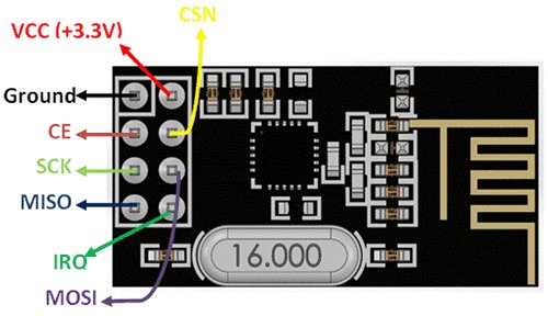
The module has on operating voltage from 1.9V to 3.6V (typically 3.3V) and consumes very less current of only 12mAduring normal operation which makes it battery efficient and hence can even run on coin cells. Even though the operating voltage is 3.3V most of the pins are 5V tolerant and hence can be directly interfaced with 5V microcontrollers like Arduino. Another advantage of using these modules is that, each module has 6 Pipelines. Meaning, each module can communicate with 6 other modules to transmit or receive data. This makes the module suitable for creating star or mesh networks in IoT applications. Also they have a wide address range of 125 unique ID’s, hence in a closed area we can use 125 of these modules without interfering with each other.
Interfacing nRF24L01 with Arduino
In this tutorial we will learn how to interface the nRF24L01 with Arduino by controlling the servo motor connected with one Arduino by varying the potentiometer on the other Arduino. For the sake of simplicity we have used one nRF24L01 module as transmitter and the other is receiver, but each module can be programmed to send and receive data individually.
The circuit diagram to connect the nRF24L01 module with Arduino is shown below. For varity, I have used the UNO for the receiver side and Nano for the transmitter side. But the logic for connection remains the same for other Arduino boards like mini, mega as well.
Receiver side: Arduino Uno nRF24L01 module connections


As said earlier the nRF24L01 communicates with the help of SPI protocol. On Arduino Nano and UNO the pins 11, 12 and 13 are used for SPI communication. Hence we connect the MOSI, MISO and SCK pins from nRF to the pins 11, 12 and 13 respectively. The pins CE and CS are user configurable, I have used pin 7 and 8 here, but you can use any pin by altering the program. The nRF module is powered by the 3.3V pin on Arduino, which in most cases will work. If not, a separate power supply can be tried. Apart from interfacing the nRF I have also connected a servo motor to pin 7 and powered it through the 5V pin on Arduino. Similarly the transmitter circuit is shown below.
Transmitter side: Arduino Nano nRF24L01 module Connections

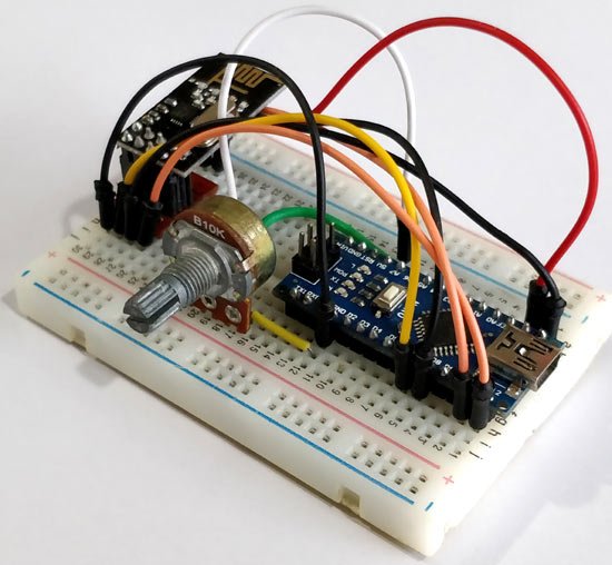
The connections for the transmitter is also the same, additionally I have used a potentiometer connected across the 5V ad Ground pin of Arduino. The output analog voltage which will vary from 0-5V is connected to the A7 pin of the Nano. Both the boards are powered through the USB port.
Working with nRF24L01+ Wireless Transceiver Module
However in order to make our nRF24L01 to work free from noise we might want to consider the following things. I have been working on this nRF24L01+ for a long time and learnt the following points which can help you from getting hit on a wall. You can try these when the modules did not work the normal way.
1. Most of the nRF24L01+ modules in the market are fake. The cheap ones that we can find on Ebay and Amazon are the worst (Don’t worry, with few tweaks we can make them work)
2. The main problem is the power supply, not your code. Most of the codes online will work properly, I myself have a working code which I personally tested, Let me know if you need them.
3. Pay attention because the modules which are printed as NRF24L01+ are actually Si24Ri (Yes a Chinese product).
4. The clone and fake modules will consume more power, hence do not develop your power circuit based on nRF24L01+ datasheet, because Si24Ri will have high current consumption about 250mA.
5. Beware of Voltage ripples and current surges, these modules are very sensitive and might easily burn up. (;-( fried up 2 modules so far)
6. Adding a couple capacitors (10uF and 0.1uF) across Vcc and Gnd of the module helps in making your supply pure and this works for most of the modules.
Still if you have problems report on comment section or read through this, or ask your questions on our forum.
Also check our pervious project on creating a Chat room using nRF24L01.
Programming nRF24L01 for Arduino
It has been very easy to use these modules with Arduino, due to the readily available library created by maniacbug on GitHub. Click on the link to download the library as ZIP folder and add it to your Arduino IDE by using the Sketch -> Include Library -> Add .ZIP library option. After adding the library we can begin programming for project. We have to write two programs, one is for the transmitter side and the other for receiver side. However as I told earlier each module can work both as a transmitter and receiver. Both the programs are given at the end of this page, in the transmitter code the receiver option will be commented out and in the receiver program the transmitter code will be commented out. You can use it if you are trying a project in which the module has to work as both. The working of the program is explained below.
Like all programs we begin by including the header files. Since the nRF uses SPI protocol we have included the SPI header and also the library that we just downloaded. The servo library is used to control the servo motor.
#include <SPI.h>
#include “RF24.h”
#include <Servo.h>
The next line is the important line where we instruct the library about the CE and CS pins. In our circuit diagram we have connected CE to pin 7 and CS to pin 8 so we set the line as
RF24 myRadio (7, 8);
All the variables that are associated with the RF library should be declared as a composite variable structure. In this program the variable msg is used to send and receive data from the RF module.
struct package
{
int msg;
};
typedef struct package Package;
Package data;
Each RF module has an unique address using which it can send data to the respective device. Since we are having only one pair here, we set the address to zero in both transmitter and receiver but if you have multiple module you can set the ID to any unique 6 digit string.
byte addresses[][6] = {“0”};
Next inside the void setup function we initialize the RF module and set to work with 115 band which is free from noise and also set the module to work in minimum power consumption mode with minimum speed of 250Kbps.
void setup()
{
Serial.begin(9600);
myRadio.begin();
myRadio.setChannel(115); //115 band above WIFI signals
myRadio.setPALevel(RF24_PA_MIN); //MIN power low rage
myRadio.setDataRate( RF24_250KBPS ) ; //Minimum speed
myservo.attach(6);
Serial.print(“Setup Initialized”);
delay(500);
}
void WriteData() function writes the data passed to it. As told earlier the nRF has 6 different pipes to which we can read or write data, here we have used 0xF0F0F0F066 as address to write data. On the receiver side we have to use the same address on ReadData() function to receive the data that was written.
void WriteData()
{
myRadio.stopListening(); //Stop Receiving and start transminitng
myRadio.openWritingPipe(0xF0F0F0F066);//Sends data on this 40-bit address
myRadio.write(&data, sizeof(data));
delay(300);
}
void WriteData() function reads the data and puts it in a variable. Again out of 6 different pipes using which we can read or write data here we have used 0xF0F0F0F0AA as address to read data. This means the transmitter of the other module has written something on this address and hence we are reading it from the same.
void ReadData()
{
myRadio.openReadingPipe(1, 0xF0F0F0F0AA); //Which pipe to read, 40 bit Address
myRadio.startListening(); //Stop Transminting and start Reveicing
if ( myRadio.available())
{
while (myRadio.available())
{
myRadio.read( &data, sizeof(data) );
}
Serial.println(data.text);
}
}
Apart from these lines the other lines in the program are used for reading the POT and converting it to 0 to 180 using map function and send it to the Receiver module where we control the servo accordingly. I have not explained them line by line since we have already learnt that in our Servo Interfacing tutorial.
Controlling Servo Motor using nRF24L01 wirelessly
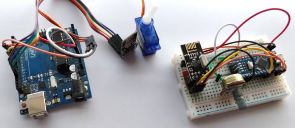
Once you are ready with the program upload the transmitter and receiver code (given below) on respective Arduino boards and power them up with USB port. You can also launch the serial monitor of both the boards to check what value is being transmitted and what is being received. If everything is working as expected when you turn the POT knob on transmitter side the servo on the other side should also turn accordingly.
The complete working of the project is demonstrated in the video below. It is quite normal for not getting these modules to work on first try, If you have faced any problem check the code and wiring again and try the above given trouble shooting guidelines. If nothing works post your problem on the forums or in the comment section and I will try to resolve them.
Code for Transmitter Part:
/*Transmit POT value through NRF24L01 using Arduino
*
* Pin Conections
* CE – 7
MISO – 12
MOSI – 11
SCK – 13
CS – 8
POT-A7
*/
#include <SPI.h>
#include “RF24.h”
RF24 myRadio (7, 8);
struct package
{
int msg = 0;
};
byte addresses[][6] = {“0”};
typedef struct package Package;
Package data;
void setup()
{
Serial.begin(9600);
myRadio.begin();
myRadio.setChannel(115); //115 band above WIFI signals
myRadio.setPALevel(RF24_PA_MIN); //MIN power low rage
myRadio.setDataRate( RF24_250KBPS ) ; //Minimum speed
delay(500);
Serial.print(“Setup Initialized”);
}
void loop()
{
int Read_ADC = analogRead(A7);
char servo_value = map (Read_ADC, 0, 1024, 0,180);
if (servo_value>1)
data.msg = servo_value;
WriteData();
delay(50);
// ReadData();
//delay(200);
}
void WriteData()
{
myRadio.stopListening(); //Stop Receiving and start transminitng
myRadio.openWritingPipe( 0xF0F0F0F0AA); //Sends data on this 40-bit address
myRadio.write(&data, sizeof(data));
Serial.print(“\nSent:”);
Serial.println(data.msg);
delay(300);
}
void ReadData()
{
myRadio.openReadingPipe(1, 0xF0F0F0F066); // Which pipe to read, 40 bit Address
myRadio.startListening(); //Stop Transminting and start Reveicing
if ( myRadio.available())
{
while (myRadio.available())
{
myRadio.read( &data, sizeof(data) );
}
Serial.print(“\nReceived:”);
Serial.println(data.msg);
}
}
Code for Receiver Part:
/*CE – 7
MISO – 12
MOSI – 11
SCK – 13
CS – 8
Recently tested with nano
*/
#include <SPI.h>
#include “RF24.h”
#include <Servo.h>
Servo myservo;
RF24 myRadio (7, 8);
struct package
{
int msg;
};
typedef struct package Package;
Package data;
byte addresses[][6] = {“0”};
void setup()
{
Serial.begin(9600);
myRadio.begin();
myRadio.setChannel(115); //115 band above WIFI signals
myRadio.setPALevel(RF24_PA_MIN); //MIN power low rage
myRadio.setDataRate( RF24_250KBPS ) ; //Minimum speed
myservo.attach(6);
Serial.print(“Setup Initialized”);
delay(500);
}
int Servo_value;
int Pev_servo_value;
void loop()
{
ReadData();
delay(50);
Pev_servo_value = Servo_value;
Servo_value = data.msg;
while (Pev_servo_value< Servo_value)
{
myservo.write(Pev_servo_value);
Pev_servo_value++;
delay(2);
}
while (Pev_servo_value> Servo_value)
{
myservo.write(Pev_servo_value);
Pev_servo_value–;
delay(2);
}
//data.msg = “nothing to send”;
//WriteData();
// delay(50);
}
void ReadData()
{
myRadio.openReadingPipe(1, 0xF0F0F0F0AA); //Which pipe to read, 40 bit Address
myRadio.startListening(); //Stop Transminting and start Reveicing
if ( myRadio.available())
{
while (myRadio.available())
{
myRadio.read( &data, sizeof(data) );
}
Serial.print(“\nReceived:”);
Serial.println(data.msg);
}
}
void WriteData()
{
myRadio.stopListening(); //Stop Receiving and start transminitng
myRadio.openWritingPipe(0xF0F0F0F066);//Sends data on this 40-bit address
myRadio.write(&data, sizeof(data));
Serial.print(“\nSent:”);
Serial.println(data.msg);
delay(300);
}
Source: Interfacing nRF24L01 with Arduino: Controlling Servo Motor
- What pins are used for SPI communication with nRF24L01 on Arduino Uno and Nano?
The MOSI, MISO and SCK pins are connected to Arduino pins 11, 12 and 13 respectively. - Which pins are used for CE and CS in this tutorial?
CE is connected to pin 7 and CS (CSN) to pin 8 in the provided example, but they are user configurable. - What operating voltage does the nRF24L01 require?
The module operates from 1.9V to 3.6V, typically 3.3V, and is powered from the Arduino 3.3V pin or a separate supply. - How is the potentiometer connected on the transmitter side?
The potentiometer is connected across 5V and Ground and its output goes to analog pin A7 on the Nano. - What library is recommended to use with nRF24L01 on Arduino?
The tutorial recommends the RF24 library by maniacbug available on GitHub and adding it as a ZIP library in the Arduino IDE. - What data rate and channel settings are used in the example code?
The example sets the channel to 115 and the data rate to RF24_250KBPS (250 kbps) with RF24_PA_MIN power level. - How do you improve stability if nRF24L01 modules are noisy or unreliable?
Add decoupling capacitors (10uF and 0.1uF) across Vcc and Gnd and ensure a stable power supply; consider using a separate supply if needed. - Can each nRF24L01 module both send and receive?
Yes, each module is a transceiver and can be programmed to send and receive, but they operate half-duplex (send or receive at a time). - What addresses are used for writing and reading in the example code?
The transmitter writes to address 0xF0F0F0F0AA and the receiver reads from 0xF0F0F0F0AA; the code also shows using 0xF0F0F0F066 in complementary functions.