Summary of Interfacing LabVIEW With Arduino
Summary: This article explains how to interface LabVIEW with an Arduino Uno using LINX and LabVIEW Interface for Arduino. It lists required software and steps to create a graphical LED blink program in LabVIEW, upload LINX firmware to the Arduino via the LINX Firmware Wizard, select the serial COM port, and run the VI to toggle the Arduino onboard LED.
Parts used in the Interfacing LabVIEW With Arduino:
- LabVIEW (software)
- NI VISA (software)
- VI Package Manager (software)
- Arduino IDE (software)
- LINX (VI Package Manager library)
- LabVIEW Interface for Arduino (VI Package Manager library)
- Arduino board (Arduino Uno)
- Arduino USB cable
Interfacing LabVIEW With Arduino
In previous article of Getting Started with LabVIEW, we have seen about LabVIEW and how it can be graphically programmed and executed in computer (software level). Now in this article we learn about How to Interface LabVIEW with Arduino Board.
Requirements
To interface LabVIEW with Arduino, you require the following software’s and hardware’s,
- LabVIEW (software)
- NI VISA (software)
- VI packet manager (software)
- Arduino IDE (software)
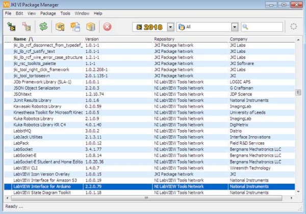
- LINX, (this will be available inside VI package manager, open VI package manager and search for it, double click on it. You will reach to an installation window. Click install button visible to you in that window.)
- LabVIEW Interface for Arduino, this will be available inside VI package manager, open VI package manager and search for it, double click on it. You will reach to an installation window. Click install button visible to you in that window, as shown below

Why do we interface Arduino with LabVIEW?
As mentioned earlier in this article, LabVIEW is a graphical programming language. Arduino has its program in lines of code, but when LabVIEW is integrated with Arduino the lines of code are converted into a pictorial program that is quite easily understandable, and the time taken for its execution is also half.
LED Blink with Arduino & LabVIEW
- Launch the LabVIEW.
- To launch LabVIEW .
- Now start graphical coding.
- In Block diagram window, right click select Makerhub >> LINX >> Open, drag & drop the Open box. Then create a control by right clicking the first wire tip and selecting Create >> Control. Thus created a Serial port.
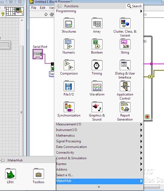
- In Block diagram window, right click and select Makerhub >> LINX >> Close. Drag & drop Close.
- In Block diagram window, right click and select Makerhub >> LINX >> Digital >>Write. Drag & drop Write. Then create a controls on second and third tip of wires by right clicking each individually and selecting Create >> Control. Thus created a D0 channel and Output Value.
- In Block diagram window, right click and select Structures >> While loop. Drag the While loop across the Digital write. Then create a Shift register by right clicking on the While loop.
- In Block diagram window, right click and select Makerhub >> LINX >> Utilities >> Loop rate. Drag & drop it inside the While loop.
- In Block diagram window, right click select Boolean >> or. Drag & drop or inside the While loop.
- In Block diagram window, right click and select Timing >> Wait(ms). Drag & drop Wait(ms) into the While loop and create a constant for it by right clicking on the wire tip which is left most to the Wait(ms) and select Create >> Constant.
- In Front panel window, right click and select Boolean >> Stop button. Now stop button appears in the Block diagram window. Drag & drop it inside the While loop.
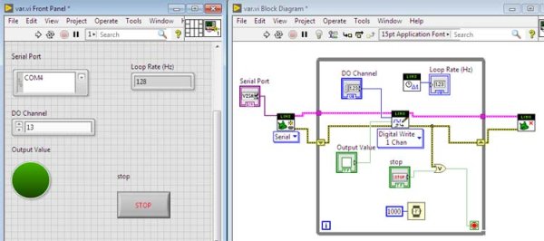
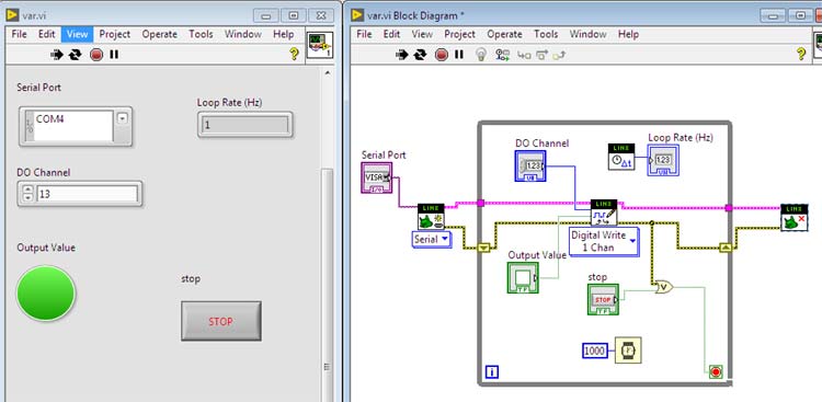
- Now by connecting all these created blocks using wiring connections, you can build the Graphical LED blink program to interface with your Arduino hardware.
Connect the LabVIEW code with Arduino
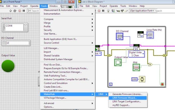
- After building the graphical code, select Tools >> Makerhub >> LINX >> LINX Firmware wizard.
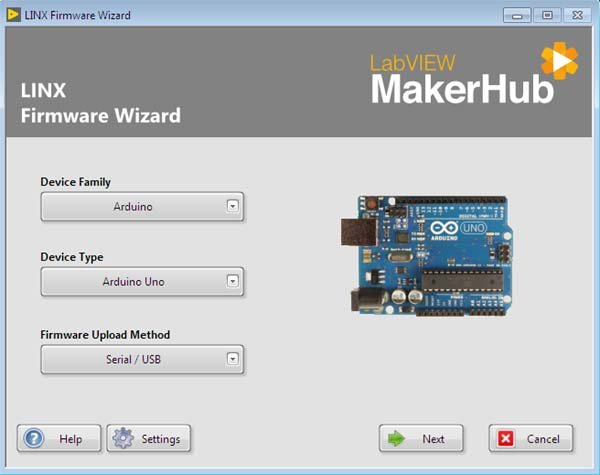
- Now LINX Firmware wizard window open’s, in that select Device Family as Arduino; Device type as Arduino Uno ; Firmware Upload Method as Serial/USB. Then click Next.
- Then connect the Arduino board to your PC using Arduino USB cable.
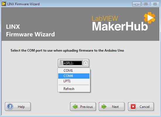
- Now in Next window select the Arduino port by clicking to the drop down list. Select COM4. Then click Next twice.
- Then click Finish button.
- Now you have setup the serial port and interfaced Arduino board with LabVIEW.
Run the Program
- Now select the Continuously Run Icon, then in the front panel window select the port and enter the digital pin.
- Then by switching the Output Value (which acts as an On & Off switch), you can see the in-built LED of the Arduino board blinking till the Output Value is turned Off .
Complete process is also explained in the video below.
Source : Interfacing LabVIEW With Arduino
- What software is required to interface LabVIEW with Arduino?
LabVIEW, NI VISA, VI Package Manager, Arduino IDE, LINX, and LabVIEW Interface for Arduino are required. - How do you create the LED blink program in LabVIEW?
Use the block diagram to place LINX Open, Digital Write, LINX Close, add a While loop with a shift register, Loop Rate, OR, Wait(ms) with a constant, and a Stop button, then wire them together. - How is the Arduino firmware set up for LabVIEW?
Run Tools >> Makerhub >> LINX >> LINX Firmware Wizard, select Device Family Arduino and Arduino Uno, choose Serial/USB firmware upload, select the COM port, and finish to upload firmware. - Which Arduino model is referenced in the article?
The Arduino Uno is referenced. - How do you select the Arduino serial port in LabVIEW?
In the LINX Firmware Wizard and in the front panel port control, choose the appropriate COM port from the drop-down list (example COM4). - How do you run the LabVIEW VI to blink the LED?
Select the Continuously Run icon, choose the port and digital pin on the front panel, and toggle the Output Value to blink the onboard LED. - Why interface Arduino with LabVIEW?
LabVIEW converts Arduino code into a graphical program that is easier to understand and can reduce execution time. - Where do you obtain LINX and LabVIEW Interface for Arduino?
They are available inside the VI Package Manager; search for them and click install.