Summary of Measuring PPM from MQ Gas Sensors using Arduino (MQ-137 Ammonia)
Since the industrial age, human progress has harmed the environment, making air quality monitoring vital. This article explains connecting any MQ-series gas sensor to an Arduino and converting readings to PPM. Using MQ-137 as an example, it shows hardware setup (sensor, RL resistor, analog read), calculating Ro in clean air, measuring Rs under gas, deriving Rs/Ro, extracting slope and intercept from the datasheet log-log graph, and using a logarithmic formula to compute PPM. It includes Arduino code and an LCD display example, plus practical tips on RL selection, sensor heating time, and module hacking.
Parts used in the MQ-137 Ammonia PPM Measurement Project:
- MQ-137 gas sensor (standalone or module)
- Arduino (any compatible board with analog input)
- RL resistor (recommended 47kΩ; example module had 1kΩ)
- Multimeter (to measure RL on module)
- Wires/jumpers
- 16x2 LCD display
- Connections for LCD: Arduino pins 8,9,10,11,12,13
- Power supply (5V for sensor and Arduino)
- Soldering tools (for replacing or adding RL on module)
Since the industrial age, we humans have been progressing quickly. As we make advancements, we simultaneously harm our environment, leading to its eventual degradation. Currently, the issue of global warming is a concerning danger and even the quality of the air we breathe is becoming a serious concern. Monitoring air quality is becoming increasingly important. In this article, we will discover how to connect any MQ series gas sensor to an Arduino and display the output in PPM (parts per million). PPM can be stated as milligrams per liter (mg/L) as well.
MQ-series Gas sensors
- Carbon Dioxide (CO2) : MG-811
- Carbon Monoxide (CO): MQ-9
- Total Volatile Organic Compounds (TVOCs): CCS811
- Equivalent Carbon Dioxide (eCO2): CCS811
- Metal Oxide (MOX): CCS811
- Ammonia: MQ-137
- Air Quality: MQ-135
- LPG, Alcohol, Smoke: MQ2
We have already used MQ2 for smoke sensing and MQ-135 for Air quality monitoring project. Here I will be using the MQ-137 sensor from sainsmart to measure ammonia in ppm. With the sensor in hand I went through all the available tutorials and found that there has no proper documentation on how to measure the gas in ppm. Most tutorials either deal with only the Analog values or introduce some constants which are not reliable for measuring all type of gas. So after fiddling around online for a long time I finally found how to use these MQ series gas sensors to measure ppm using Arduino. I am explaining things from the bottom without any libraries so that you can use this article for any Gas sensor available with you.
Preparing your Hardware:
The MQ gas sensors are available either as a module or as a standalone sensor for purchase. If you only need to measure ppm, it is recommended to purchase the sensor separately as the module is only suitable for utilizing the Digital pin. If you have already bought the module, you will need to do a simple hack that will be explained later. At this moment, let’s suppose you have acquired the sensor.
Simply connect one end of ‘H’ to the power source and the other end to the ground. Next, mix together both of the A’s and both of the B’s. Connect one set of wires to the power source and connect the other set to the analog pin. The presence of resistor RL is crucial for the proper functioning of the sensor. Be sure to remember the value you are using, we suggest a value of 47k.
If you have already purchased a module, then you should track your PCB traces to find the value of your RL in the board. Grauonline has already done this work for us and the circuit diagram of the MQ gas sensor board is given below.
The resistor RL (R2) is connected from the Aout pin to ground in the module, allowing its value to be measured using a multimeter in resistance mode between the Vout pin and Vcc pin. In my sainsmart MQ-137 gas sensor, the RL value was 1K and was placed in the location indicated in the image below.
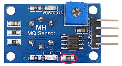
Nevertheless, the website asserts that it offers a variable potentiometer of RL, but this is inaccurate since the circuit diagram clearly shows that the potentiometer is actually used to adjust the voltage for the op-amp and is unrelated to RL. Therefore, we need to solder the SMD resistor (1K) by hand and install our own resistor between the Ground and Vout pin to serve as RL. According to the datasheet suggestion, we will be using a 47K resistor value for RL since it is the best option.
Approach to Measure PPM from MQ Gas Sensors:
Now that the RL value is known, let’s move on to how we can measure ppm using these sensors. The starting point for all sensors is their datasheet. Here is the MQ-137 Datasheet, ensure to locate the accurate datasheet for your sensor. Within the datasheet, we only require a single graph depicting (Rs/Ro) versus PPM for our calculations. Get it and store it in a convenient place. Below is the one for my sensor.
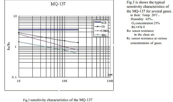
It appears that the MQ137 sensor is capable of detecting NH3, C2H6O, and CO gases. However, my focus is solely on the NH3 values. Nevertheless, you can employ the same technique to determine ppm for any sensor of your choosing. This graph is our sole means of determining the ppm value, and by calculating the Rs/Ro ratio on the X-axis, we can determine the ppm value on the Y-axis. In order to determine Rs/Ro’s value, we must determine the value of both Rs and Ro. Rs is the sensor resistance when exposed to gas, while Ro is the sensor resistance in clean air.
Yes, this is the strategy, let’s figure out how we can evade detection.
Calculating the Value of Ro at Clean Air:
Note that in the graph value of Rs/Ro is constant for air (thick blue line) so we can use this to our advantage and say that when the sensor is working in fresh air the value of Rs/Ro will be 3.6 refer the picture below
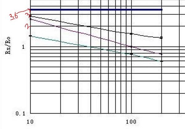
Rs/Ro = 3.6
From the datasheet we also get to have a formula for calculating the value of Rs. The formula is shown below. If you are interested to know how this formula is derived you can read through jay con systems, I would also like to credit them in helping me to sort this out.

In this equation, Vc represents the supply voltage (+5V) and RL represents the calculated value (47K for my sensor). By writing a simple Arduino code, we can determine the VRL value and consequently figure out the Rs value as well. Below is an Arduino Program provided to read the analog voltage (VRL) of the sensor, calculate the value of Rs using this formula, and then display it in the serial monitor. The explanation of the program is detailed in the comments, so I’m not going to repeat it here to keep this article brief.
/*
 * Program to measure the value of R0 for a know RL at fresh air condition
 * Program by: B.Aswinth Raj
 * Website: www.circuitdigest.com
 * Dated: 28-12-2017
 */
//This program works best at a fresh air room with temperaure Temp: 20℃, Humidity: 65%, O2 concentration 21% and when the value of Rl is 47K

#define RL 47  //The value of resistor RL is 47K
void setup() //Runs only once
{
  Serial.begin(9600); //Initialise serial COM for displaying the value
}

void loop() {
  float analog_value;
  float VRL;
  float Rs;
  float Ro;
  for(int test_cycle = 1 ; test_cycle <= 500 ; test_cycle++) //Read the analog output of the sensor for 200 times
  {
    analog_value = analog_value + analogRead(A0); //add the values for 200
  }
  analog_value = analog_value/500.0; //Take average
  VRL = analog_value*(5.0/1023.0); //Convert analog value to voltage
  //RS = ((Vc/VRL)-1)*RL is the formulae we obtained from datasheet
  Rs = ((5.0/VRL)-1) * RL;
  //RS/RO is 3.6 as we obtained from graph of datasheet
  Ro = Rs/3.6;
  Serial.print("Ro at fresh air = ");
  Serial.println(Ro); //Display calculated Ro
  delay(1000); //delay of 1sec
}
Note: The value of Ro will be varying, allow the sensor to pre-heat at least for 10 hours and then use the value of Ro.
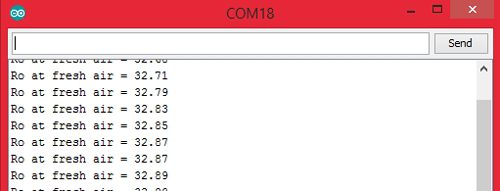
I concluded the value of Ro to be 30KΩ for my sensor (when RL is 47kΩ). Yours might slightly vary.
Measure the value of Rs:
Having found the value of Ro, we can now readily determine the value of Rs using the formulae provided earlier. Please be aware that the Rs value determined earlier is based on clean air and may differ when ammonia is detected in the air. Determining the worth of Rs is a minor task that can be easily handled in the end program.
Relating Rs/Ro ratio with PPM:
Now that we know how to measure the value of Rs and Ro we would be able to find its ratio (Rs/Ro). Then we can use the chart (shown below) to relate to the corresponding value of PPM.
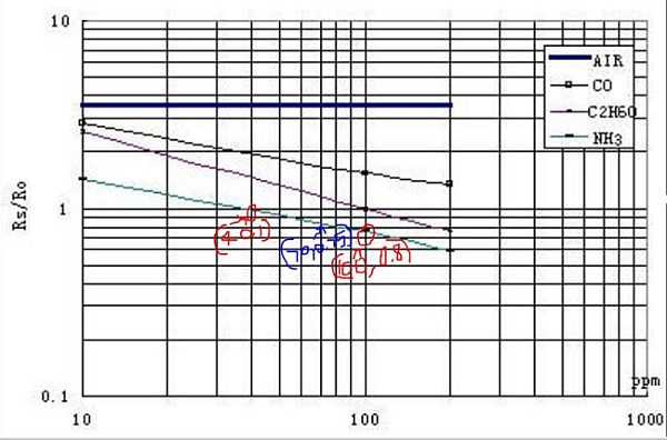
Although the NH3 line (cyan colour) appears to be linear it is actually not linear. The appearance is because the scale is divided un-uniformly for appearance. So the relating between Rs/Ro and PPM is actually logarithmic which can be represented by the below equation.
log(y) = m*log(x) + b

where,
y = ratio (Rs/Ro)
x = PPM
m = slope of the line
b = intersection point
To find the values of m and b we have to consider two points (x1,y1) and (x2,y2) on our gas line. Here we are working with ammonia so the two points I have considered is (40,1) and (100,0.8) as shown in the picture above (marked as red) with red marking.
m = [log(y2) - log(y1)] / [log(x2) - log(x1)]
m = log(0.8/1) / log(100/40)
m = -0.243
Similarly for (b) let’s get the midpoint value (x,y) from the graph which is (70,0.75) as shown in picture above (marked in blue)
b = log(y) - m*log(x)
b = log(0.75) - (-0.243)*log(70)
b = 0.323
That’s it now that we have calculated the value of m and b we can equate the value of (Rs/Ro) to PPM using the below formula
PPM = 10 ^ {[log(ratio) - b] / m}
Program to calculate PPM using MQ sensor:
Below is the entire code for calculating PPM with a MQ sensor. A few key points are detailed in the following lines.
Prior to moving forward with the program, we must input the values of Load resistance (RL), Slope (m), Intercept (b), and the Resistance in fresh air (Ro). The method for acquiring these values has been previously described, so now we can simply input them.
#define RL 47  //The value of resistor RL is 47K
#define m -0.263 //Enter calculated Slope
#define b 0.42 //Enter calculated intercept
#define Ro 30 //Enter found Ro value
Then read the Voltage drop across the sensor (VRL) and convert it to Voltage (0V to 5V) since the analog read will only return values from 0 to 1024.
VRL = analogRead(MQ_sensor)*(5.0/1023.0); //Measure the voltage drop and convert to 0-5V
Now, that the value of VRL is calculated you can use the formula discussed above to calculate the value of Rs and the also the ratio (Rs/Ro)
ratio = Rs/Ro; // find ratio Rs/Ro
Finally, we can calculate the PPM with our logarithmic formula and display it on our serial monitor as shown below
double ppm = pow(10, ((log10(ratio)-b)/m)); //use formula to calculate ppm
Serial.print(ppm); //Display ppm
Showing PPM value on Hardware with Arduino and MQ-137:
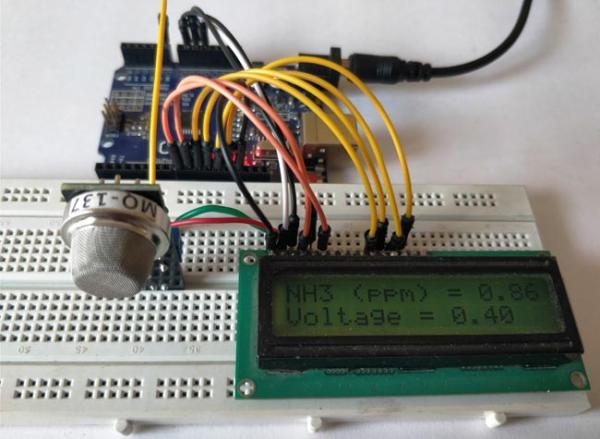
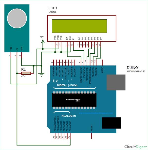
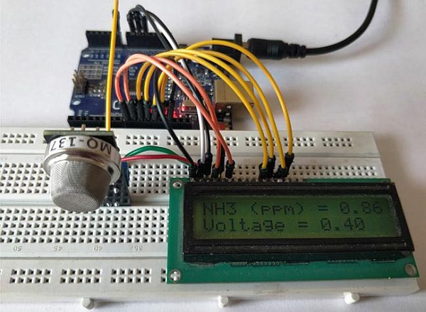
Enough of all the theory let us build a simple circuit with the sensor and LCD to display the value of gas in PPM. Here the sensor I am using is MQ137 which measures ammonia, the circuit diagram for my set up is shown below.

Connect your sensor and your LCD as shown in the Circuit diagram and upload the code given at the end of the program. You have to modify the Ro value as explained above. Also make the changes in parameter values if you are using any other resistor as RL other than 4.7K.
Leave your set-up powered for at least 2 hours before you take any readings, (48 hrs is recommended for more accurate values). This time is called the heating time, during which the sensor warms up. After this, you should be able to see the value of PPM and the voltage displayed on your LCD screen as shown below.
To confirm the connection between the values and ammonia, put the setup in a closed container and introduce ammonia gas to see if the values rise. I don’t have a PPM meter to calibrate this set-up, so it would be helpful if someone with a meter could test it and inform me.
You can view the video below to see how the readings changed depending on the presence of ammonia. I hope you grasped the idea and had a good time learning it. If you have any uncertainties, feel free to leave them in the comments or seek more extensive assistance on the forum provided.
/*
* Program to measure gas in ppm using MQ sensor
* Program by: B.Aswinth Raj
* Website: www.circuitdigest.com
* Dated: 28-12-2017
*/
#define RL 47 //The value of resistor RL is 47K
#define m -0.263 //Enter calculated Slope
#define b 0.42 //Enter calculated intercept
#define Ro 20 //Enter found Ro value
#define MQ_sensor A0 //Sensor is connected to A4
#include <LiquidCrystal.h> //Header file for LCD from https://www.arduino.cc/en/Reference/LiquidCrystal
const int rs = 8, en = 9, d4 = 10, d5 = 11, d6 = 12, d7 = 13; //Pins to which LCD is connected
LiquidCrystal lcd(rs, en, d4, d5, d6, d7);
void setup() {
lcd.begin(16, 2); //We are using a 16*2 LCD display
lcd.print(“NH3 in PPM”); //Display a intro message
lcd.setCursor(0, 1); // set the cursor to column 0, line 1
lcd.print(“-CircuitDigest”); //Display a intro message
delay(2000); //Wait for display to show info
lcd.clear(); //Then clean it
}
void loop() {
float VRL; //Voltage drop across the MQ sensor
float Rs; //Sensor resistance at gas concentration
float ratio; //Define variable for ratio
VRL = analogRead(MQ_sensor)*(5.0/1023.0); //Measure the voltage drop and convert to 0-5V
Rs = ((5.0*RL)/VRL)-RL; //Use formula to get Rs value
ratio = Rs/Ro; // find ratio Rs/Ro
float ppm = pow(10, ((log10(ratio)-b)/m)); //use formula to calculate ppm
lcd.print(“NH3 (ppm) = “); //Display a ammonia in ppm
lcd.print(ppm);
lcd.setCursor(0, 1); // set the cursor to column 0, line 1
lcd.print(“Voltage = “); //Display a intro message
lcd.print(VRL);
delay(200);
lcd.clear(); //Then clean it
}
Video:
Source: Measuring PPM from MQ Gas Sensors using Arduino (MQ-137 Ammonia)
- How do you wire an MQ sensor for analog PPM measurement?
Connect heater pins H to Vcc and Gnd, tie the A pins together and B pins together, connect one set to Vcc and the other to analog input through RL to ground; ensure RL is present between Vout and ground. - Can I use the MQ module directly to get PPM values?
The module digital output is not suitable for PPM; you should use the standalone sensor or modify the module by measuring and replacing the RL resistor to read analog values. - What value of RL should I use?
The article recommends 47kΩ for RL based on the datasheet suggestion; module RL may differ (example module had 1kΩ) and should be replaced if needed. - How do you determine Ro for the sensor?
Measure sensor voltage in fresh air after preheating, compute Rs from VRL, then use the datasheet air Rs/Ro value (3.6 for MQ-137) to calculate Ro. - How long should the sensor preheat before taking Ro measurements?
Allow at least 10 hours for preheat to measure Ro; for general readings leave powered 2 hours and 48 hours is recommended for accuracy. - How is PPM calculated from sensor readings?
Compute VRL from analogRead, calculate Rs, find ratio Rs/Ro, then use the logarithmic formula PPM = 10^((log10(ratio)-b)/m) with m and b derived from the datasheet curve. - How do you find slope m and intercept b for the gas curve?
Pick two points on the sensor datasheet Rs/Ro versus PPM curve to compute m = [log(y2)-log(y1)]/[log(x2)-log(x1)] and b = log(y) - m*log(x) from a midpoint. - Does the article provide Arduino code for PPM and LCD display?
Yes, the article includes full Arduino sketches: one to compute Ro in fresh air and another to compute PPM and display NH3 ppm and voltage on a 16x2 LCD. - What should I do to verify the sensor responds to ammonia?
Place the setup in a closed container, introduce ammonia gas, and observe if the displayed PPM and readings increase as shown in the article.