Summary of Interactive Touchless Light
This article details a DIY touchless controller using capacitive sensing to blend RGB LED colors. The author explains the theory of measuring time differences via resistance and capacitance, then lists necessary components like an Arduino Uno, resistors, LEDs, and materials for the case. The guide covers prototyping with insulated aluminum foil sensors, wiring, and provides C++ code that averages sensor data to smooth output and control light intensity based on hand proximity.
Parts used in the Touchless Light Controller:
- 2 x 22M Ohm resistors
- 3 x 330 Ohm resistors
- Wires
- Breadboard
- Circuit board
- Multiple common Cathode RGB LEDs
- Aluminium foil
- Cling wrap
- Arduino Uno
- Tape
- MDF wood (50 x 50 x 1.8 CM)
- Acrylic plexiglas (50 x 50 x 0.3 CM)
- Fine sandpaper
- Wood-glue
- Veneer
- Acrylic glue
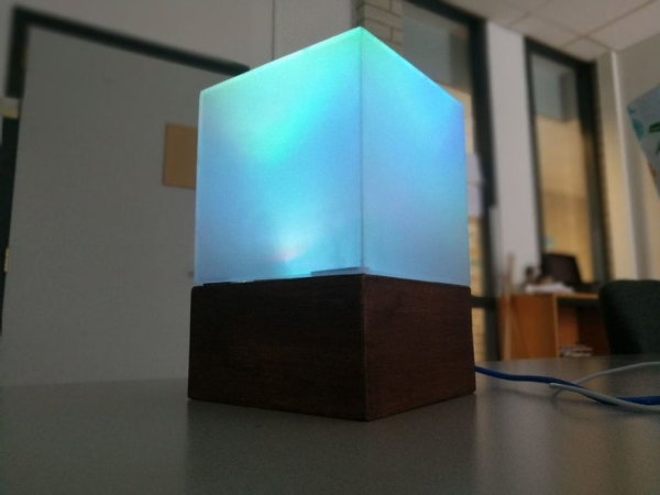
Hi everyone! I’d like to share the project I have been working on here. I got inspired to experiment with capacitive touch sensing through a project in my university. I found out about this technology through instructables and used the things I learned here and from other places on the internet to build my own touch-less controller, which I use to blend different RGB values to create interesting light colors.
For starters, when I started this project I knew next to nothing about either electronics nor capacitive touch sensing.
Some problems I ran in to early on were caused by misunderstanding what actually happens. So a short introduction from how I understand it:
A capacitive sensor uses multiple components, mainly:
A capacitor (in this project we use aluminium foil, but its also possible to use conductive fluids etc),
wires (ofcourse, its electronics)
and a resistor, anything under 10 MOhm is too small a resistance for more than direct touch.
the way it works is by measuring a difference in time between point A and point B. From the start pin it sends a signal to an endpin, the time it takes is measured with a timer. By decreasing the resistance value (by moving a capacitor (in this case your hand) closer to the capacitor of the sensor(the aluminium foil) this time shortens, the difference in time is what the sensor gives back as a value.
Due to the sensor being affected by capacitive surfaces the data can be wildly erratic due to interference. This can be solved for a large part by correctly insulating the capacitor and also by using a ground (I will show how later on) .
So now that is out of the way we can start inventorying all the stuff we need:
Step 1: What Do We Need?
Electronics:
- 2 x 22M Ohm + resistors (the bigger the resistance value the further away your sensor reacts, I personally used 22M Ohm, the minimum to get usable data I experienced was 10M Ohm)
- 3x 330 Ohm resistors
3.Wires
- Breadboard
- Circuit board (mine had continouos copper strips)
- Multiple common Cathode RGB Leds (I used 8, but you can have more or less depends on how much light you want)
7.Aluminium foil
- Cling wrap
9.Arduino Uno
- Tape
The Case:
- Wood I used 50 x 50 x 1.8 CM MDF(you can use anything really. It depends on the effect you want and the tools you have at your disposal)
- Acrylic plexiglas I used 50 x 50 x 0.3 CM(or any other transparent/translucent material like rice paper)
3.Sandpaper (fine sandpaper)
4.Wood-glue
5.veneer (optional)
6.Acrylic glue
Tools:
Wire stripper
Soldering iron + tin
Stanley knife
drill
Saw (I used a table saw)
Step 2: Prototyping:
Now we have everything and we can start making a prototype to see how it works:
Prep work:
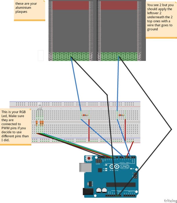
Cut out 4 rectangles from the aluminium foil (Mine are about 10 cm by 5 cm), wrap these in cling wrap to insulate them from direct touch and stick a wire to the aluminium foil. I just taped a stripped end to the foil (as long as they stay in contact).
To make sure the aluminium is safely insulated I wrapped in cling wrap and ironed it between papers (just for a few seconds so it doesn’t completely melt).
Then set up the circuit as seen in the image.
Pin 4 is used as a send pin for both sensors, while the receive pins are pin 2 and 5. You could use multiple send pins but it causes trouble since they are not perfectly in sync.
use this setup for debugging purposes before soldering everything together, to make sure that everything truly works as intended.
Step 3: Code:
Now we have everything and we can start debugging the sensors.
To use my code you should download the capacitive sensing library from Arduino and install it according to the directions given by the reference page: Click me
The code: (I’m not great at coding, so if you know how to do it better please do)
include //import the code library
CapacitiveSensor cs_4_2 = CapacitiveSensor(4,2); //Send pin = 4, receive are 2 and 5
CapacitiveSensor cs_4_5 = CapacitiveSensor(4,5);
const int redPin = 11;
const int greenPin = 10;
const int bluePin = 9;
const int numIndexR = 10; // array size
const int numIndexG = 10;
int colorR = 0;
int colorG = 0;
float colorB = 0;
int indexR [numIndexR];
int posIndexR = 0;
long totalR = 0; //it needs to be a long because the total of my array was to big for an integer.
int averageR = 0;
int indexG [numIndexG];
int posIndexG = 0;
long totalG = 0;
int averageG = 0;
void setup()
{
pinMode(redPin, OUTPUT);
pinMode(greenPin, OUTPUT);
pinMode(bluePin, OUTPUT);
for (int thisIndexR = 0; thisIndexR < numIndexR; thisIndexR++) { //sets the array to 0
indexR [thisIndexR] = 0;
}
for (int thisIndexG = 0; thisIndexG < numIndexG; thisIndexG++) {
indexG [thisIndexG] = 0;
}
colorR = 255; //turns on all leds colors
colorG = 255;
colorB = 255;
Serial.begin(9600);
}
void loop()
{
long start = millis();
long total1 = cs_4_2.capacitiveSensor(10); //Save the raw sensor data to a variable
long total2 = cs_4_5.capacitiveSensor(10);
if (total1 >= 4500){        //cap the sensor values to a usable maximum, this is not the same for every resistor value and also might differ a bit from environment to environment you might need to tweak this to your own needs.
  total1 = 4500;
  }

if (total2 >= 4500){
  total2 = 4500;
  }

totalR = totalR - indexR[posIndexR]; //this here creates an array that continuously adds a sensor output and produces the average.
indexR[posIndexR] = total1;
totalR = totalR + indexR[posIndexR];
posIndexR = posIndexR + 1;


if (posIndexR >= numIndexR){
  posIndexR = 0;
  }

averageR = totalR / numIndexR; //we use the average instead of the raw data to smooth out the output, it slows the process down slightly but it also creates a really nice smooth flow.

totalG = totalG - indexG[posIndexG];
indexG[posIndexG] = total2;
totalG = totalG + indexG[posIndexG];
posIndexG = posIndexG + 1;

if (posIndexG >= numIndexG){
  posIndexG = 0;
  }

averageG = totalG / numIndexG;
if (averageR >= 2000 ){ // we don’t want the leds to constantly changes value unless there is input from your hand, so this makes sure all lower environmental readings are not taken into account.
colorR = map(averageR, 1000, 4500, 255, 0);
      analogWrite (redPin, colorR);
}
else if (averageR <= 2000){
colorR = 255;
analogWrite (redPin, colorR);
}if (averageG >= 1000 ){
colorG = map(averageG, 1000, 4500, 255, 0);
      analogWrite (greenPin, colorG);
}
else if (averageG <= 1000){
       colorG = 255;
       analogWrite (greenPin, colorG);
}
if (colorR <= 125 && colorG <= 125){ //B works a bit different because I only used 2 sensors so I mapped B on both sensors
colorB = map(colorR, 255, 125, 0, 127.5) + map(colorG, 255, 125, 0, 127.5);
analogWrite (bluePin, colorB);
}
else{
colorB = map(colorR, 255, 125, 127.5, 0) + map(colorG, 255, 125, 127.5, 0);
if (colorB >= 255){
colorB = 255;
}
if (colorB <= 0){
colorB = 0;
}
analogWrite (bluePin, colorB);
}
Serial.print(millis() - start);        //this is for debugging purposes
Serial.print("\t");

Serial.print(colorR);
Serial.print("\t");
Serial.print(colorG);
Serial.print("\t");
Serial.println(colorB);

delay(1);
}
What this code does is extracting the raw data from the sensor (this data will always be slightly erratic due to all the different factors that affect the sensor) and it puts the raw data continuously in an array, when the array reaches is max value (in my case 10) it purges the last value and adds a new one. Each time a value is added it calculates the average value and puts it in a new variable. This average variable is used to map a value to a value from 0 to 255, this is the value that we write to the RGB pins to increase the brightness of each channel (the channels being R G and B).
Now if you upload your code to the arduino and you open the serial monitor you should be seeing the RGB values lower when you hover your hand over each sensor also the light color of the led should change.
Source: Interactive Touchless Light
- How does a capacitive sensor work?
It measures the difference in time between a start pin sending a signal and an endpin receiving it; moving a capacitor closer shortens this time. - What is the minimum resistance value needed for usable data?
The minimum experienced was 10M Ohm, as anything under 10 MOhm is too small for more than direct touch. - Can I use conductive fluids instead of aluminium foil?
Yes, while this project uses aluminium foil, conductive fluids are also possible for the capacitor component. - How do you solve erratic data caused by interference?
Data can be solved largely by correctly insulating the capacitor and using a ground. - Which pins are used for the send and receive signals?
Pin 4 is used as the send pin, while pins 2 and 5 act as the receive pins. - Why is an array used in the code?
An array continuously adds sensor output to produce an average, which smooths out the erratic raw data. - What happens if the average sensor reading is below 2000 for red?
The color value resets to 255, turning the red channel fully on. - How is the blue LED brightness calculated?
Blue works differently because only two sensors were used, so its value is mapped based on both the red and green sensor inputs.