Summary of How to Make an Arduino Capacitance Meter
This tutorial explains building three Arduino-based capacitance meters that together measure ~10 pF to 3900 μF, using RC time-constant timing with a few resistors. It compares accuracy across ranges, provides schematics, code, and a downloadable quick-start guide so you can label capacitors without a digital multimeter.
Parts used in the Arduino Capacitance Meter Project:
- Arduino (Uno or compatible)
- Resistors (various values for different measurement ranges)
- Capacitors of known values (for calibration/testing)
- Wires/jumpers
- Breadboard or prototyping board
- USB cable (for Arduino power and programming)
- Optional: enclosure or mounting hardware
With all the different ways capacitors are labeled, figuring out the values of your capacitors can be challenging. Especially if you don’t have a digital multi-meter to test them. In this tutorial, I’ll show you how to build three different capacitance meters using an Arduino and a couple resistors. After finishing this project, you’ll be able to measure all of your capacitors and label them for future reference.
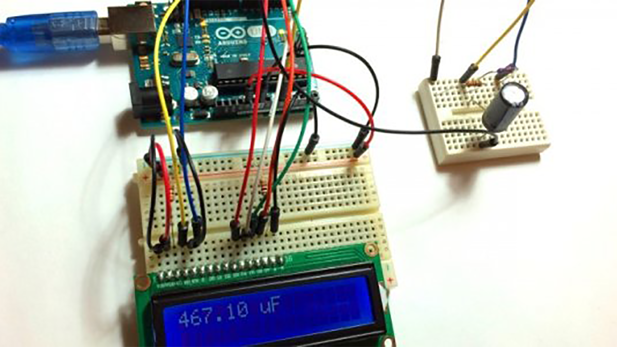
When I was testing these capacitance meters, I couldn’t find one that was able to accurately measure the full range of commonly used capacitors. One meter would accurately measure values in the 1000 μF range, but it would fail in the nF and pF range. Another capacitance meter was accurate in the nF and pF ranges, but failed in the μF range. So, I’ll show you three different meters that together will cover a range of about 10 pF to 3900 μF.
BONUS: I made a quick start guide for this tutorial that you can download and go back to later if you can’t set this up right now. It covers all of the steps, diagrams, and code you need to get started.
To compare the error in their measurements, I tested the output of each capacitance meter described below against capacitors of known values. This graph shows the range of values each capacitance meter is able to measure accurately:
Before we start building the circuits, let’s get a little background on how we can use the Arduino to measure capacitance…
How the Arduino Can Measure Capacitance
Each Arduino capacitance meter relies on a property of resistor capacitor (RC) circuits- the time constant. The time constant of an RC circuit is defined as the time it takes for the voltage across the capacitor to reach 63.2% of its voltage when fully charged:
Read more: How to Make an Arduino Capacitance Meter
- What range of capacitance can the three meters measure together?
About 10 pF to 3900 μF. - How does the Arduino measure capacitance in these meters?
By timing the RC circuit time constant, specifically the time to reach 63.2% of charging voltage. - Do you need a digital multimeter to use this project?
No, the project is intended to measure and label capacitors without a digital multimeter. - Why are three different meters used instead of one?
Because a single meter could not accurately cover the full range; different meters perform accurately in different ranges (pF, nF, μF). - Is there a ready quick start guide available?
Yes, the author provides a downloadable quick start guide covering steps, diagrams, and code. - How was measurement accuracy compared?
The author tested each meter against capacitors of known values and plotted measurement error across ranges. - Can the described meters measure both very small and very large capacitors accurately?
Together they cover very small (pF) to large (μF) capacitors accurately, whereas individual meters have limited accurate ranges.