Summary of How to control a Servo using Arduino
This project uses an Arduino to control a servo via two pushbuttons: one moves the servo left, the other moves it right. While the servo turns, a corresponding LED lights to indicate direction. The Arduino Servo library handles servo motion; the IR sensor is mentioned as being rotated by the servo in a related use. The code initializes pins for buttons, LEDs, and servo, and constrains motion between set minimum and maximum angles.
Parts used in the Servo Button Control Project:
- Arduino
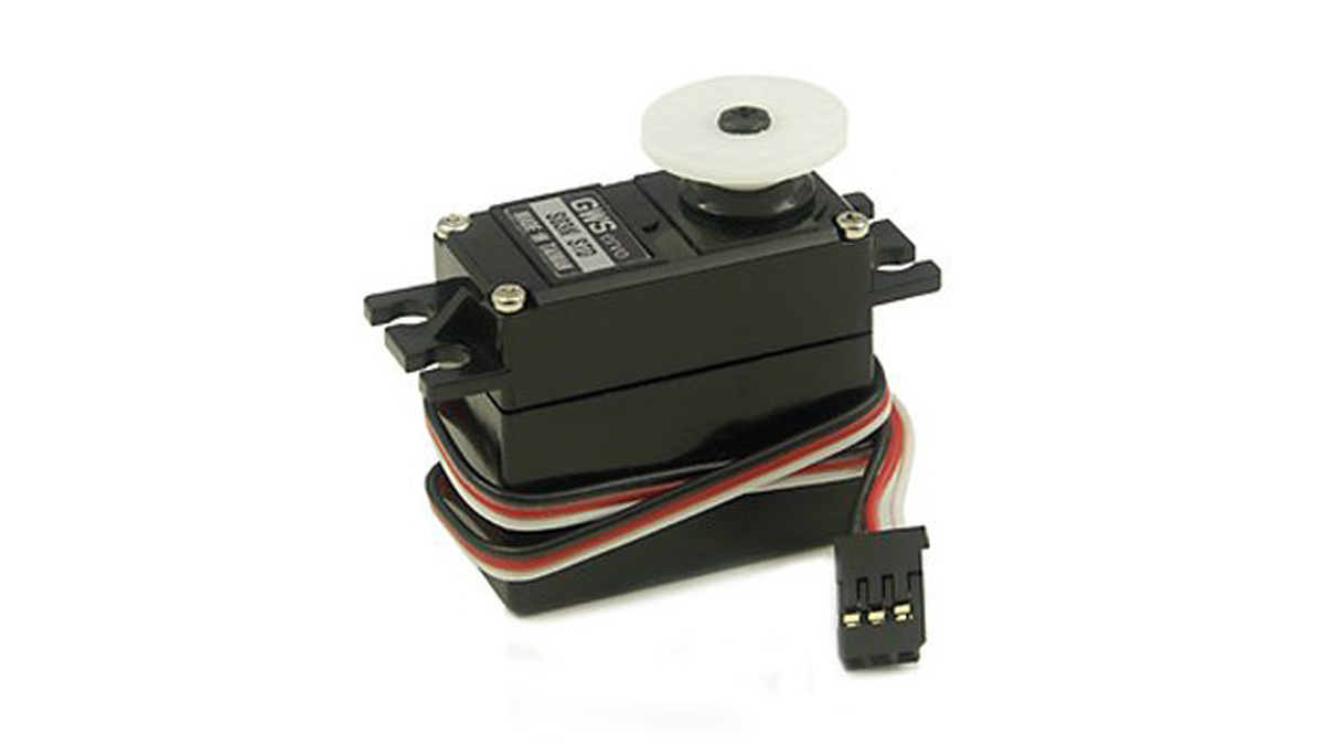
- Servo motor
- Two pushbuttons (left and right)
- Two indicator LEDs
- Resistors for LEDs and buttons
- Wires/jumper cables
- Breadboard or prototyping board
- IR sensor (used in the project application)
In this one, servo is programmed to be controlled by two buttons, one turns servo to the left and the other one turns it to the right. When the servo is turning, corresponding LED will be switched on to indicate the operation.
Result:
Because Arduino has built-in library for controlling servo, which makes servo a really easy kit to use. In this project, I will be using a servo to turn the IR sensor around constantly.
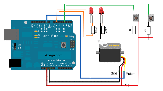
This is the circuit Diagram:
This is the code:
| // Oscar’s Project // // There are 2 input buttons (turn left and right), when button is pressed, the servo turns and corresponding LED is lit up. |
#include
Servo myservo; // create servo object to control a servo
// a maximum of eight servo objects can be created
int pos = 90; // variable to store the servo position
const int maxDeg = 160;
const int minDeg = 5;
const int leftPin = 3;
const int rightPin = 2;
const int led1Pin = 6; // indicator
const int led2Pin = 5; // indicator
const int outputPin = 9; // pwm function will be disabled on pin 9 and 10 if using servo
int leftPressed = 0;
Major Components in Project
Arduino
For more detail: How to control a Servo using Arduino
- How is the servo controlled in the project?
The servo is controlled by the Arduino using the built-in Servo library and two input buttons to move left or right. - Can LEDs indicate servo direction?
Yes, corresponding LEDs are switched on when the servo turns to indicate the operation. - What limits are set for servo motion?
The code uses minimum and maximum degree limits; minDeg is 5 and maxDeg is 160. - Which pins are used for the left and right buttons?
The example uses pin 3 for left and pin 2 for right. - Which pins are used for the indicator LEDs?
The example uses pin 6 for one LED and pin 5 for the other LED. - Which pin is used for the servo output?
The servo output is assigned to pin 9 in the code. - Does using a servo affect PWM on any pins?
Yes, the code notes that PWM function will be disabled on pin 9 and 10 if using servo. - Is the IR sensor part of the servo application?
Yes, the project mentions using a servo to turn the IR sensor around constantly.