Summary of IoT Using ESP8266-01 and Arduino
Today’s tutorial shows how to build a WiFi‑enabled smart home controller using an Arduino (e.g., Nano) and an ESP8266‑01 module acting as a web server. It explains wiring, changing the ESP8266 baud from 115200 to 9600 via AT commands, creating a simple HTML/CSS/jQuery control panel that sends GET requests with pin codes (e.g., 111/110), Arduino code to parse requests and toggle outputs, and how to drive low‑voltage LEDs then scale to AC loads using a two‑channel relay.
Parts used in the Smart Home System:
- Arduino board (any model; Arduino Nano used in tutorial)
- ESP8266-01 WiFi module
- LEDs (for testing)
- 1 kΩ resistor
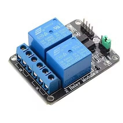
- Two-channel relay module
- Wires/jumper cables
- 3.3V power source for ESP8266-01
- USB cable or power source for Arduino
- Computer with Arduino IDE and Serial Monitor
Ever asked how to control any device from any place in the world? In this tutorial, we’ll learn how to control things wirelessly over WiFi.
Story
Introduction
Today, we will build a device that connects to the internet and allow the user to control his/her home remotely over wifi. We will use the Arduino board(any model will do the job well) with the ESP8266-01 wifi module to make this device. Let’s get started!
What’s a smart home?
Smart home technology uses devices such as linking sensors, features and other appliances connected to the internet of things (IoT) that can be remotely monitored, controlled or accessed and provide services that respond to the needs of the users.Wikipedia
Working Scenario
The ControlPanel
We will build a simple web page that will work as a control panel for the user allows him to control any home appliance connected to our system. To build the web page we will use:
- HTML
- CSS
- Jquery
The Embedded Hardware
The web page sends some orders to the ESP8266-01 which is working as a web server connected to the Arduino board. And according to the incoming data, the Arduino board will take some actions like turning on the bulb, turning off the TV and in this part, we will use:
- Arduino
- ESP8266-01
Getting Started with the ESP8266-01
As we stated before, we need our Arduino board to get connected to the Internet but the Arduino Nano the version which we are using today doesn’t have that feature. So, we will use the ESP8266-01 wifi module to add the wifi feature to our tiny Arduino board.
there are a lot of ESP wifi modules models out there, which one should I choose?! Well, almost all the ESP family wifi modules out there will do the job well but each one has its own features and specifications. I encourage you to look at each one specifications and features to choose the most suitable one for your needs.
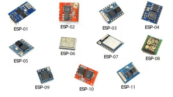
According to my needs, I found the ESP8266-01 is the most suitable one and that’s for many reasons. It’s very famous in the makers community. As a result, it got a very solid online community that you can find an answer to almost any question or problem you face with this awesome small module. Also, its price is very cheap(around 1.5$).
Also, it’s very easy to use with the Arduino board since its a Serial wifi module it can communicate with the Arduino board over the serial communication. It has a built-in Microcontroller which means that you can use it as a standalone microcontroller and wifi module in one combo which is super cool. It has built-in two GPIOs. Only with 1.5$, you will get all of these features which is super cool, actually. Let’s get a closer look at this module.
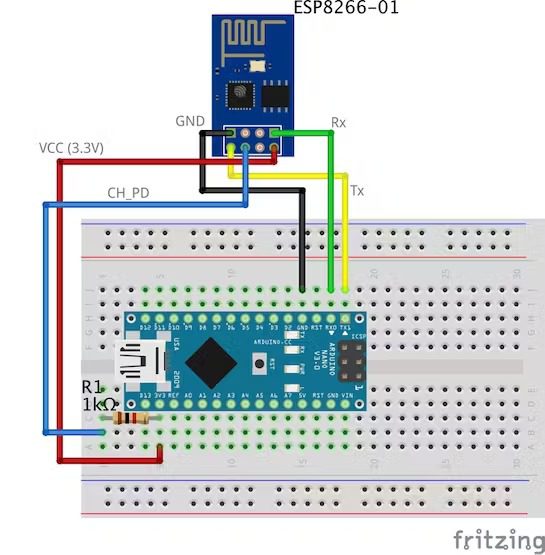
ESP8266-01 Pinout
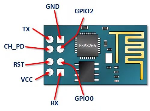
- VCC: connect to +3.3V power source. Don’t connect it with a 5V source it will get damaged.
- GND: -ve pin, connect it to the ground of your circuit.
- CH_PD: chip enables pin – Active HIGH. Connect it to a logic value HIGH to allow the module to boot up.
- RST: Chip Reset pin – Active LOW, when it pulled LOW it Resets the module.
- GPIO0, GPIO2: General purpose input/output pins.
- Tx: connect to the Rx of the microcontroller(Arduino) to establish serial communication.
- Rx: connect to the Tx of the microcontroller(Arduino) to establish serial communication.
ESP8266-01 Configuration
As we stated before the ESP8266-01 module communicates with the Arduino board over the Serial communication. Which means that we need to connect it with the Arduino’s Serial pins 0, 1(Tx, Rx). But the problem here is that these pins will be busy because we will use the Arduino Serial monitor alongside the ESP8266-01 for debugging purposes. So, we need to find another two Serial communication pins to use them with the ESP8266-01.
Fortunately, Arduino made this easy. There’s a library called “SoftwareSerial” which developed to allow serial communication on other digital pins of the Arduino, using software to replicate the functionality. For example, by using this library I can set the pins 2, 3(SoftwareSerial) as Rx and Tx alongside the pins 0, 1(Hardware Serial).
“SoftwareSerial” library works great as long as the transmission speed is less than 19, 200 baud. But, there’s a small problem here! the ESP8266-01 wifi module comes from the factory programmed to communicate at speed 115, 200 baud which is somehow hard at the “SoftwareSerial” library to communicate at. So, we need to reprogram our wifi module to set the communication speed to 9600 baud which works pretty good with the “SoftwareSerial” library. To do that we will use some “AT Commands”.
Changing the ESP8266-01 communication speed
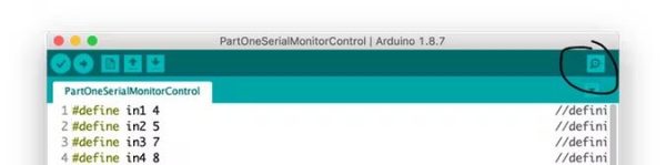
First step: Upload an empty program to the Arduino board
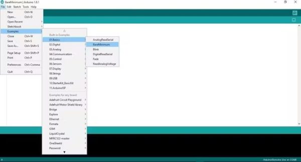
At this step, we are uploading an empty code to the Arduino board. Just to be sure that there’s nothing is Executing in the background by the Arduino board.
Second Step: Wiring the ESP8266-01 with the Arduino board
To Reconfigure the ESP8266-01 and change the communication speed(baud rate) we use the AT-commands. Simply, AT commands are some instructions used to control modems, mobile phones, Bluetooth modules, wifi modules, GSM Modules.
With these commands we can get basic information about our mobile phone or GSM Modules like the name of the manufacturer, model number, IMEI and so on.“AT” is an abbreviation for “ATtention” and it’s called AT-commands because every command starts with “AT”. The “AT” prefix is not a part from the commands itself it just tells the module the start of the commands.
Some Important AT Commands
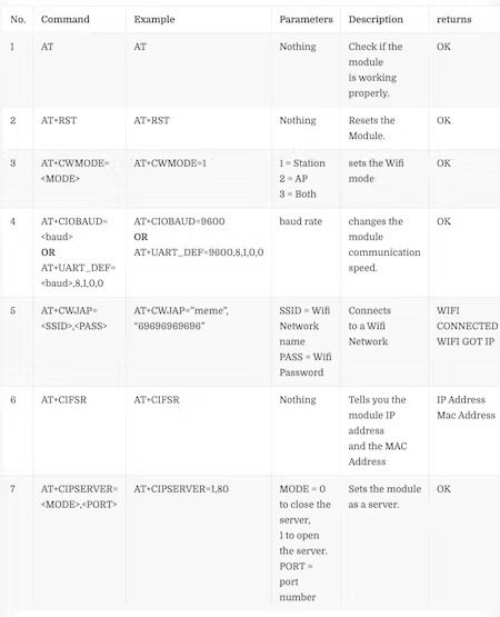
Command number “4” depends on your ESP8266-01 firmware version, if this command doesn’t work with you AT+CIOBAUD=<baud> Try this one AT+UART_DEF=<baud>,8,1,0,0
Step 1: Open the Serial Monitor
Step 2: Set the Communication speed to 115, 200 baud
![]()
As we stated before, the ESP comes from the manufacturer programmed to communicate at speed 115, 200 baud. So we need to set the Arduino communication speed to 115, 200 too for the first time only then we will change that later. Also, you should select “Both NL & CR”.
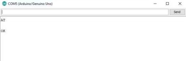
Step 3: Send “AT” and wait for the response to be sure that the ESP module is hearing you.
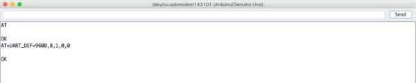
Step 4: Now, change the ESP8266-01 communication speed
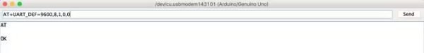
My ESP8266-01 module loaded firmware is 1.6. and this command AT+UART_DEF=<baud>,8,1,0,0 works well for me. If it doesn’t work with you, try this AT+CIOBAUD=<baud>. If it responds with “OK” now your ESP module communication baud rate changed from 115, 200 baud to 9600 baud. CONGRATS!
Let’s change the Serial monitor communication speed back to 9600 and send “AT” again to see if the ESP module can hear us at the new Speed(9600) or not.
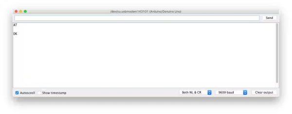
LOOK! it’s working. the ESP8266-01 now can communicate with the Arduino board at 9600 baud rate instead of 115, 200 baud rate.
Now, let’s try to connect with the Wifi network
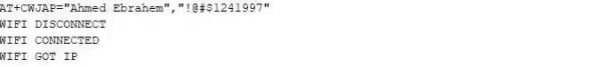
Once you press enter, the ESP8266-01 will search for this network and connect with it. If the process succeeds it will return this
WIFI CONNECTED
WIFI GOT IP
At this point, we successfully changed the ESP8266-01 communication speed from 115, 200 baud to 9600 baud. Now, we need to build the control panel(Web Page) which the user will use to control his home appliances. So, let’s build it!
What’s the Internet?
Actually, the internet is a wire buried under the ground it can be fiber optics, copper, or even a satellite but the internet is simply a wire. Any two computers connected to that wire can communicate. If the computer is connected directly to that wire it’s called a server and if it not connected directly to that wire it’s called a client.
Server: Is a special computer that runs a specific Operating system like Apache, this special computer saves some web pages, files, databases on its disk drive. Any server connected to the internet has a unique IP Address like 172.217.171.228, the IP address is just like a phone number helps people to find each other easily. Since that IP Address is not very easy for humans to remember. So, we just gave it a name google.com(Domain name).
Client: It’s a computer like what you and I are using every day, it’s connected indirectly to the internet through an internet service provider(ISP) and it also has a unique IP address.
Working Scenario
Simply, it starts with a request sent from a web browser(Client) like google chrome, Firefox and ends with the response received from the webserver.
You entered the website URL makesomestuff.org in a browser from a computer(client), then this browser sends a request to the webserver hosts the website, the webserver then returns a response contains HTML page or any other document format to the browser to display it.
Exactly, that’s what we need to do today in our project. We need to send a request from the web browser(Client) to the ESP8266-01(Webserver) which both of them are connected to the same local network. This request contains some data which tells the Arduino what to do turn on or off a light bulb. So, let’s build the web page!
Building The Web Page
To build our web page we have to deal with HTML, CSS, Javascript. If you never heard about these names before, don’t worry I got you.
HTML: Stands for “HyperText markup language”. We use it to build any web page main structure. Like adding some buttons, images, paragraphs, headers, tables, and many more elements. It consists of a series of elements which tell the browser how to display the web page content. These elements represent by something called tags.

CSS: It stands for cascading style sheet. After building the web page main structure, you need to make this structure looks nice here comes CSS to make some styling. It’s a language that describes the style of an HTML element. It consists of some selectors and deceleration blocks.

Javascript: It’s a programming language that we will use to make the web page more interactive like adding some animations, maps and it allows us to make some complex things on the web page. Mainly, we will use it today to send an HTTP request from the client(web browser) to the webserver(ESP8266-01) to take some actions like turning on or off a light bulb.
Build The Web Page Structure
To easily understand the upcoming explanation, I recommend Reading this cool HTML intro.
As we see our control panel is very simple. It contains two headers each one has a different size, one image, and two buttons one for turning on an LED and the second one for turning it off.
Code
<!DOCTYPE html>
<html>
<head>
    <title>Smart Home System</title>
</head>
<body>
    <h1> Smart Home Control Panel</h1>
    <h4>Sorry But I'm a Meme Addict!</h4>
    <img src="dogMeme.jpg" width="400px" height="400px">
    <br>
    <button id="111" class="button">LAMP ON</button>
    <br>
    <button id="110" class="button">LAMP OFF</button>
</body>
</html>
Code Explanation
- <!DOCTYPE html>: declaration defines that this document is an HMTL5 document.
- <html>: the root element of an HTML page.
- <head>: element contains meta information about the page.
- <title>: element specifies the title of the document. this title appears on the web page browser tab.
- <body>: element contains the visible web page content.
- <h1>: element defines a large element.
- <h4>: element defines a smaller header. when the header value decreases the font decreases.
- <img>: element adds an image to the web page. the image that you want to display should be in the same project folder.
- <br>: advance the cursor to a new line.
- <button>: element adds a button to the page content.
Each button is our web page has very important two attributes the id, and the class attributes. we will talk about why we assigned these two values to the buttons in the Jquery code explanation.
Styling The Web Page
To easily understand the upcoming explanation, I recommend Reading this cool CSS intro.
Now, the web page looks nicer (NOT TOO MUCH xD) we gave it a cool green background color, we make the page content centered aligned, and we change the headers font color and font family which made the web page more alive. We used CSS to do all of this styling stuff.
Code
<!DOCTYPE html>
<html>
<head>
    <title>Smart Home System</title>
</head>
<body style="background-color: seagreen; color: seashell; text-align: center;">
    <h1> Smart Home Control Panel</h1>
    <h4>Sorry But I'm a Meme Addict!</h4>
    <img src="dogMeme.jpg" width="400px" height="400px">
    <br>
    <button style="margin: 10px;" id="111" class="button">LAMP ON</button>
    <br>
    <button style="margin:10px;" id="110" class="button"> LAMP OFF</button>
</body>
</html>
Code Explanation
We added some few lines of code to make our web page looks nicer. We added style="background-color: seagreen; color: seashell; text-align: center;" inside the body tag to make all the web page content in the center of the page and to set the background color to seagreen also to set the font color to seashell.
Also, we added style="margin: 10px;" inside the two button tags to set a margin of 10 pixels around the four sides of each button.
Sending a Request To The Webserver
To easily understand the upcoming explanation, I recommend Reading this cool Jquery intro.
Now, after building our web page structure and styling it we need to add some functionality to the two buttons which we added earlier in the web page. we need when the user clicks the “LAMP ON” button his/her browser sends a request contains some unique data to the server(ESP8266-01) this unique data tells the Arduino to turn on the lamp. The same thing with the second button “LAMP OFF” when the user clicks it, the browser will send a request contains some unique data to the server(ESP8266-01) this unique data tells the Arduino to turn off the lamp. Let’s take a look at the code.
<!DOCTYPE html>
<html>
<head>
    <title>Smart Home System</title>
    <script src="https://ajax.googleapis.com/ajax/libs/jquery/3.3.1/jquery.min.js"></script>
</head>
<body style="background-color: seagreen; color: seashell; text-align: center;">
    <h1> Smart Home Control Panel</h1>
    <h4>Sorry But I'm a Meme Addict!</h4>
    <img src="dogMeme.jpg" width="400px" height="400px">
    <br>
    <button style="margin: 10px;" id="111" class="button">LAMP ON</button>
    <br>
    <button style="margin:10px;" id="110" class="button"> LAMP OFF</button>
        <script>                                                        //starting Javascript.
        $(".button").click(function () {                            //if any button from the ".button" class is clicked
            var p = $(this).attr('id');                             //get this button id and store it inside the "p" variable.
            pin: p                                                  //a dictionary contains the button id to get sent to the web server.
            $.get("http://192.168.1.4:80/", {                      //then send a get request to the web server"http://192.168.1.4:80/" (":80" means port number 80) with some data in a form of dictionary {pin: p} which is the butoon id. IMPORTANT NOTE: DON'T FORGET TO CHANGE THE IP ADDRESS WITH YOUR ESP8266 NEW IP ADDRESS.
            pin: p
            });
        });
    </script>
</body>
</html>
Code Explanation
First Things First, we need to import the Jquery library in our code. So, we added this line in the head tag.<script src="https://ajax.googleapis.com/ajax/libs/jquery/3.3.1/jquery.min.js"></script>
All the magic happens in this interesting part.
 <script>                                                        //starting Javascript.
        $(".button").click(function () {                            //if any button from the ".button" class is clicked
            var p = $(this).attr('id');                             //get this button id and store it inside the "p" variable.
            pin: p                                                  //a dictionary contains the button id to get sent to the web server.
            $.get("http://192.168.1.4:80/", {                      //then send a get request to the web server"http://192.168.1.4:80/" (":80" means port number 80) with some data in a form of dictionary {pin: p} which is the butoon id. IMPORTANT NOTE: DON'T FORGET TO CHANGE THE IP ADDRESS WITH YOUR ESP8266 NEW IP ADDRESS.
            pin: p
            });
        });
    </script>
$(".button").click(function () {
When the user clicks on any button associated with the class “button”, trigger the following function.
var p = $(this).attr('id');
Get the value of the clicked button attribute “id” and store it inside the “p” variable.
pin: p
Put the variable “p” value in a dictionary (key-value) it’s key is “pin” and the value is “p” variable value.
$.get("http://172.20.10.11:80/", { pin: p });});
Then, send a GET request to the webserver which it’s IP address is “172.20.10.11”. this GET request contains the value of the attribute id pressed button.
In case the user pressed the “LAMP ON” button this id value will be 111, so the GET request header will contain some data like this pin=111. look at the next figure!
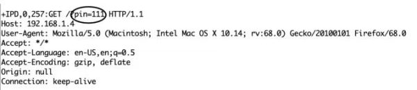
At the opposite side, if the user pressed “LAMP OFF” button the request will contain this data pin=110.
Code Logic
I know you asking now why the heck did he choose 111 and 110 specifically? Ok, Lemme answer you fam. Actually, the number 111 and 110 divides into two parts.
- Part one: is the first two numbers which are in both cases will be “11”, it refers to the Arduino pin number which the load I need to control is connected on.
- Part two: is the third number which changes between 1 and 0 depending on the clicked button. And it refers to the pin state(ON or OFF).
In the Arduino code, we will receive this data and separate these two parts from each other and save each part in a different variable, part one in variable pinNumber and the second part in variable pinState, then we will write this simple line of code to control the connected loaddigitalWrite(pinNumber, pinState);
Connecting The Load
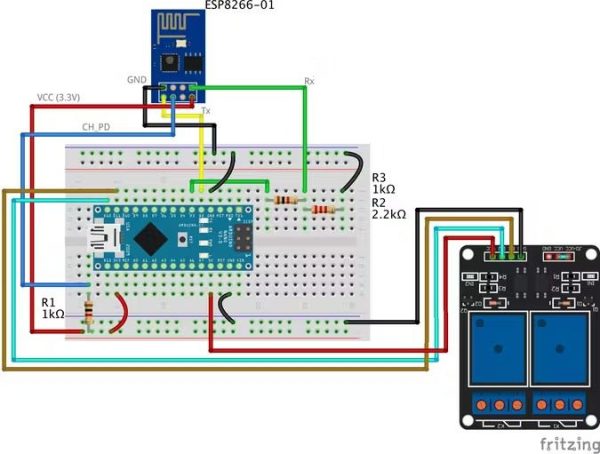
Now, we need to connect the load with the Arduino board to control it. Before connecting any high voltage device like the air conditioner or even the TV, we need to test our circuit and the code with some low voltage stuff like LEDs only to make sure that everything is working well. Here’s the wiring diagram
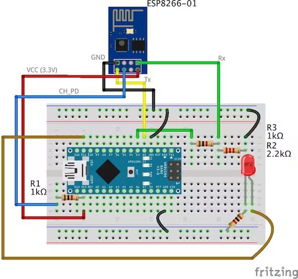
The wiring is pretty simple. We are connecting the LED positive leg to the Arduino digital pin 11, and the negative leg to the GND through a 1k ohm resistor.
Arduino Code
#include <SoftwareSerial.h>                         //including the SoftwareSerial library will allow you to use the pin no. 2,3 as Rx, Tx.
SoftwareSerial esp8266(2,3);                        //set the Rx ==> Pin 2; TX ==> Pin3.
#define serialCommunicationSpeed 9600               // <========= define a constant named "serialCommunicationSpeed" with a value 9600. it referes to the Software and hardware serial communication speed(baud rate).
#define DEBUG true                                  //make a constant named "DEBUG" and it's value true. we will use it later.
int redLED =12;                                     //assign a variable named "redLED" with an integer value 12, it refers to the pin which the red LED is connected on.
int blueLED =11;                                    //assign a variable named "blueLED" with an integer value 11, it refers to the pin which the blue LED is connected on.
void setup()
{
  pinMode(redLED,OUTPUT);                           //set the pin number 12 as an output pin.
  pinMode(blueLED,OUTPUT);                          //set the pin number 11 as an output pin.

  digitalWrite(redLED,LOW);                         //turn the red LED off at the beginning of the program.
  digitalWrite(blueLED,HIGH);                       //turn the blue LED on at the beginning of the program.
  Serial.begin(serialCommunicationSpeed);           //begin the Hardware serial communication (0, 1) at speed 9600.
  esp8266.begin(serialCommunicationSpeed);          //begin the software serial communication (2, 3) at speed 9600.
  InitWifiModule();                                 //call this user-defined function "InitWifiModule()" to initialize a communication between the ESP8266 and your access point (Home Router or even your mobile hotspot).
  digitalWrite(blueLED,LOW);                        //after finishing the initialization successfully, turn off the blue LED (just an indicator).
}
void loop()                                                         //our main program, some fun are about to start)
{
  if(esp8266.available())                                           //if there's any data received and stored in the serial receive buffer, go and excute the if-condition body. If not, dont excute the if-condition body at all.
  {
    if(esp8266.find("+IPD,"))                                       //search for the "+IPD," string in the incoming data. if it exists the ".find()" returns true and if not it returns false.
    {
      delay(1000);                                                  //wait 1 second to fill up the buffer with the data.
      int connectionId = esp8266.read()-48;                         //Subtract 48 because the read() function returns the ASCII decimal value. And 0 (the first decimal number) starts at 48. We use it to convert from ASCI decimal value to a character value.
      esp8266.find("pin=");                                         //Advance the cursor to the "pin=" part in the request header to read the incoming bytes after the "pin=" part which is the pinNumer and it's state.
      int pinNumber = (esp8266.read()-48)*10;                       //read the first Byte from the Arduino input buffer(i.e. if the pin 12 then the 1st number is 1) then multiply this number by 10. So, the final value of the "pinNumber" variable will be 10.
      pinNumber = pinNumber + (esp8266.read()-48);                  //read the second Byte from the Arduino input buffer(i.e. if the pin number is 12 then the 2nd number is 2) then add this number to the first number. So, the final value of the "pinNumber" variable will be 12.
      int statusLed =(esp8266.read()-48);                           //read the third byte from the Arduino input buffer. then save it inside the "statusLed" variable. At any case, it will be 1 or 0.
      digitalWrite(pinNumber, statusLed);                           //then turn the LED at "pinNumber" on or off depending on the "statusLed" variable value.
      Serial.println(connectionId);                                 //print the "connectionId" value on the serial monitor for debugging purposes.
      Serial.print(pinNumber);                                      //print the "pinNumber" value on the serial monitor for debugging purposes.
      Serial.print("      ");                                       //print some spaces on the serial monitor to make it more readable.
      Serial.println(statusLed);                                    //print the "statusLed" value on the serial monitor for debugging purposes.
      String closeCommand = "AT+CIPCLOSE=";                         //close the TCP/IP connection.
      closeCommand+=connectionId;                                   //append the "connectionId" value to the string.
      closeCommand+="\r\n";                                         //append the "\r\n" to the string. it simulates the keyboard enter press.
      sendData(closeCommand,1000,DEBUG);                            //then send this command to the ESP8266 module to excute it.

    }
  }
}
/******************************************************************************************************************************************************************************************
* Name: sendData
* Description: this Function regulates how the AT Commands will ge sent to the ESP8266.
*
* Params: command - the AT Command to send
*                 - timeout - the time to wait for a response
*                 - debug - print to Serial window?(true = yes, false = no)
*
* Returns: The response from the esp8266 (if there is a reponse)
*/
String sendData(String command, const int timeout, boolean debug)
{
    String response = "";                                             //initialize a String variable named "response". we will use it later.

    esp8266.print(command);                                           //send the AT command to the esp8266 (from ARDUINO to ESP8266).
    long int time = millis();                                         //get the operating time at this specific moment and save it inside the "time" variable.
    while( (time+timeout) > millis())                                 //excute only whitin 1 second.
    {
      while(esp8266.available())                                      //is there any response came from the ESP8266 and saved in the Arduino input buffer?
      {
        char c = esp8266.read();                                      //if yes, read the next character from the input buffer and save it in the "response" String variable.
        response+=c;                                                  //append the next character to the response variabl. at the end we will get a string(array of characters) contains the response.
      }
    }
    if(debug)                                                         //if the "debug" variable value is TRUE, print the response on the Serial monitor.
    {
      Serial.print(response);
    }
    return response;                                                  //return the String response.
}
/******************************************************************************************************************************************************************************************
* Name: InitWifiModule
* Description: this Function gives the commands that we need to send to the sendData() function to send it.
*
* Params: Nothing.
*
* Returns: Nothing (void).
*/
void InitWifiModule()
{
  sendData("AT+RST\r\n", 2000, DEBUG);                                                  //reset the ESP8266 module.
  //delay(1000);
  sendData("AT+CWJAP=\"PUT YOUR SSID\",\"PUT YOUR PASSWORD\"\r\n", 2000, DEBUG);        //connect to the WiFi network.
  delay (3000);
  sendData("AT+CWMODE=1\r\n", 1500, DEBUG);                                             //set the ESP8266 WiFi mode to station mode.
  delay (1000);
  sendData("AT+CIFSR\r\n", 1500, DEBUG);                                                //Show IP Address, and the MAC Address.
  delay (1000);
  sendData("AT+CIPMUX=1\r\n", 1500, DEBUG);                                             //Multiple conections.
  delay (1000);
  sendData("AT+CIPSERVER=1,80\r\n", 1500, DEBUG);                                       //start the communication at port 80, port 80 used to communicate with the web servers through the http requests.
}
code explanation
the code is pretty straightforward, we implemented two different functions InitWifiModule() and sendData()
The sendData() function job is regulating how the AT commands will get sent to the ESP8266-01 module.
the InitWifiModule() function job is to provide the sendData() function the AT commands that we need to send to the ESP8266-01.
In the loop() function we read the income HTTP request header and search for the “+IPD, ” which means that the request has successfully arrived, then we read the pin value which it will be “111” if the user clicked the “LAMP ON” button and “110” if the user clicked “LAMP OFF” button.
Don’t forget to put your wifi SSID and Password in the Arduino code line no. 103sendData("AT+CWJAP=\"PUT YOUR SSID\",\"PUT YOUR PASSWORD\"\r\n", 2000, DEBUG);
For more code explanation please read the comments in the code, it’s well documented
How It Works
After uploading the code to the Arduino board, open the Serial monitor and read the responses that the ESP module is sending.
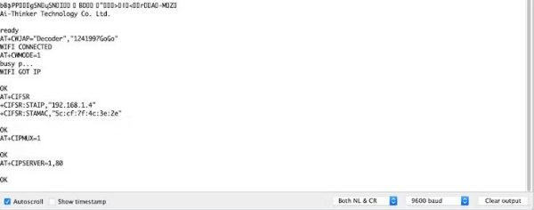
At the beginning of the program, if you see something like the previous figure with “OK” at the end of the page, it means that the ESP8266-01 module is successfully connected to your wifi (Access point) and got an IP and MAC address. Now, you can open your fancy web page and try to control some stuff.
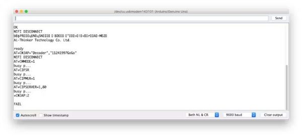
But, if you see something like the previous figure with a “FAIL” or “ERROR” at the end of the page, it means that your ESP module can’t connect to your wifi (Access point) for some reasons. Try to check if entered the right SSID and password for your network.
Adding a High Voltage Load
After we tested our code and got sure that everything is working like a charm. We need to replace this boring LED with a High voltage load like an air conditioner, TV or a light bulb. But to control all of these high voltage appliances we have to deal with relays.
What’s and why relays? Ok, the relay is a mechanical switch, which is toggled on or off by energizing a coil. It’s mainly used to control a high powered circuit using a low power signal (5V or 0V). So we can control a high powered device like an air conditioner or an AC lamp turning it on or off only by a 5V or 0V signal. Which is amazing!
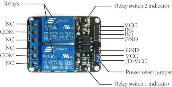
The Two-channel relay module has two control pins(IN1, IN2) these pins should get connected to two Arduino digital pins to control the state of the two coils, closes or opens the load circuit.
At the opposite side of the relay module, the COM(common) should get connected to one end of the load. The other end of the load is either connected to the NC(Normally Close) or NO(Normally open). If connected to the NO the load remains Disconnected before trigger and vice versa.
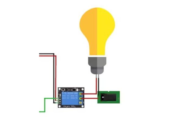
Wiring Diagram
As you see, we are using a two-channel relay module that gives us the ability to control two different AC loads. We are connecting the first relay at digital output pin11(Arduino) and the second relay to digital output pin 12(Arduino).
Make a small modification to our web page. We will add another two buttons(ON and OFF) to control the second connected load.
<!DOCTYPE html>
<html>
<head>
    <title>Smart Home System</title>
    <script src="https://ajax.googleapis.com/ajax/libs/jquery/3.3.1/jquery.min.js"></script>
</head>
<body style="background-color: seagreen; color: seashell; text-align: center;">
    <h1> Smart Home Control Panel</h1>
    <h4>Sorry But I'm a Meme Addict!</h4>
    <img src="dogMeme.jpg" width="400px" height="400px">
    <br>
    <button style="margin: 10px;" id="111" class="button">Blue LED ON</button>
    <button id="110" class="button">Blue LED OFF</button>
    <br>
    <button style="margin:10px;" id="121" class="button"> Red LED ON</button>
    <button id="120" class="button">Red LED OFF</button>
    <script>                                                        //starting Javascript.
        $(".button").click(function () {                            //if any button from the ".button" class is clicked
            var p = $(this).attr('id');                             //get this button id and store it inside the "p" variable.
            pin: p                                                  //a dictionary contains the button id to get sent to the web server.
            $.get("http://192.168.1.4:80/", {                       //then send a get request to the web server"http://192.168.1.4:80/" (":80" means port number 80) with some data in a form of dictionary {pin: p} which is the butoon id. IMPORTANT NOTE: DON'T FORGET TO CHANGE THE IP ADDRESS WITH YOUR ESP8266 NEW IP ADDRESS.
            pin: p
            });
        });
    </script>
</body>
</html>
Source: IoT Using ESP8266-01 and Arduino
- How do you add WiFi to an Arduino Nano?
Use an ESP8266-01 module connected over serial (SoftwareSerial recommended) to add WiFi to the Arduino Nano as described in the article. - Can SoftwareSerial communicate with ESP8266 at factory baud?
No, SoftwareSerial struggles at 115200 baud; the article changes the ESP8266 baud to 9600 using AT commands. - What AT command can set ESP8266 baud to 9600?
Use AT+UART_DEF=<baud>,8,1,0,0 or if unsupported try AT+CIOBAUD=<baud> as described in the article. - How does the web control panel send commands to the ESP8266?
The web page uses jQuery $.get to send HTTP GET requests with a pin parameter (e.g., pin=111) to the ESP8266 web server IP and port 80. - What do the IDs 111 and 110 mean in the project?
First two digits indicate the Arduino pin number (11) and the third digit indicates state (1 for ON, 0 for OFF), so 111 means pin 11 ON and 110 means pin 11 OFF. - How does the Arduino parse incoming web requests?
The Arduino reads serial data from esp8266, looks for +IPD,, advances to pin=, then reads three digits to derive pinNumber and statusLed as shown in the code. - How do you test before connecting high voltage loads?
First test the system with low voltage devices such as LEDs and resistors to ensure functionality before using relays for AC loads. - Why use relays for controlling AC appliances?
Relays allow a low voltage Arduino signal to switch high voltage circuits safely; the two-channel relay module controls two loads via IN1 and IN2 with COM/NO/NC terminals. - What must be configured in the Arduino code for WiFi connection?
Replace PUT YOUR SSID and PUT YOUR PASSWORD in the sendData AT+CWJAP command so the ESP8266 can join the WiFi network. - How is the ESP8266 started as a web server on port 80?
The InitWifiModule function sends AT+CIPMUX=1 and AT+CIPSERVER=1,80 to start the server listening on port 80 as shown in the article.