ABSTRACT:
There are several places which require vital notice to be displayed like colleges, railway stations, share-market, restaurants, hospitals etc. Looking into the present trend of information transfer, it is seen that vital notice take time to be displayed on the displaying boards. This latency is not anticipated in most of the cases and must be avoided. The advancement in the technologies related to wireless communication has led to the emergence of several engineering designs to aid the human requirements. This project presents a combination of wireless technology with LED Display Boards formalized by designing and integrating the hardware and software with ATmega328 microcontroller, GSM module, moving LED display. The proposed design overcome the difficulties faced by previous moving text message display modules using wired entry via computer, keyboard or remote control entry (small distance). The message is sent through a cell-phone which is accepted by the GSM module SIM 300 (master). 
Number authentication is done by ATmega328 microcontroller and the stored numbers in EEPROM is compared with the incoming number. The message will be valid only after the incoming cell phone number is validated. Authentication result is displayed on LCD whether the number is matched or not matched and the message is finally displayed on moving LED (Light emitting diode) display. Further the same SMS is itself sent by GSM module (master) to Multiple LED Display Boards which are connected via different GSM modules (slaves). So what we need
SIM 300 a GSM Module which we are going to use to receive the text message. This module needs 9V DC power supply so we are using adapter for that. Here we are using only two pins of this module to connect with Arduino or our ATmega 328/168/8 board.
Those are GND to common all grounds and make path complete for data
TX (TTL Transmitter pin) to receive signal to Microcontroller from GSM Module
Do connections same as schematic.
2) LED Matrix using Max7219 interfacing IC:
Max 7219 is an IC which we gona use to drive our LED matrix. Advantage of using this IC is we can make use of as much as IC we want in cascade so easy to make LED Matrix as much as long we want. Follow circuit diagram for connections and datasheet for more info.
3) Atmega 328 Microcontroller with own breakout board or Arduino
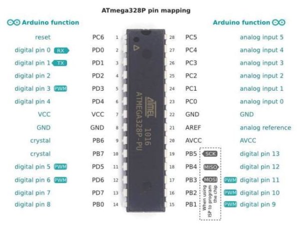
Here we are using Arduino UNO R3 but guys u have an option of making your own breakout board using Atmega 328, 168, 8 According to your application but don’t forgot to burn bootloader without that u never gona burn any code from Arduino board (To burn bootloader in blank chip please follow our link HOW TO BURN BOOTLOADER IN ATMEGA 328) next for connections refer circuit diagram. If you are using Atmega 328/168/8 with own made board then follow this pin mapping and compare it with standard Arduino.
For more detail: GSM Based Wireless Notice Board