Summary of Getting Started With BTE13-010 – Arduino Mini Clone
This guide provides essential steps to start using the BTE13-010 Arduino mini clone, including soldering pin headers, wiring, driver installation for CH340G USB-serial converter, and testing. It emphasizes specific drivers for Arduino clones and recommends prior soldering knowledge. For enhanced testing, additional components like an SG90 servo and 16x2 LCD with potentiometer are suggested. The soldering instructions highlight careful placement on a breadboard and precautions to avoid damage.
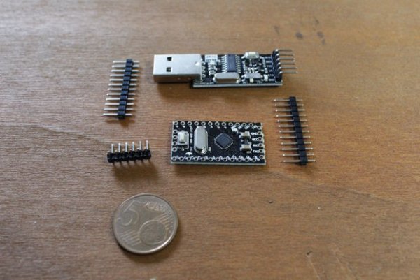
Parts used in the Getting Started With BTE13-010 – Arduino Mini Clone:
- BTE13-010 (328p 5V 16Mhz - Arduino mini clone)
- CH340G (Serial_to_USB converter)
- Connectors (usually sold with BTE13-010)
- Dupont wires (at least 5 female-to-female cables)
- SG90 Mini servo
- 16x2 LCD display
- 10kOhm linear potentiometer or 10kOhm resistor
- Tools and materials for soldering
This is a simple guide that will teach you how to get started with this cheap Arduino mini clone, covering all the steps one should do to make it work. Basically they are 4…
- Soldering PIN headers*
- Wiring it up
- Installing properly drivers**
- Testing
..and this is the minimum required that you need to follow this guide:
- BTE13-010 (328p 5V 16Mhz – Arduino mini clone)
- CH340G (Serial_to_USB converter)
- Connectors (usually sold with BTE13-010)
- Some Dupont wires (at least 5 female-to-female cables)
- Tools and materials for soldering (see Yet another tutorial on how to solder by techrm)
But if you want to make a more accurate test, you can do a simple experiment. For that, you’ll need:
- SG90 Mini servo
- 16×2 LCD display
- 10kOhm linear potentiometer or alternatively a 10kOhm resistor (to adjust the display contrast)
- Some Dupont wires
Before starting, we want to tell you that this tutorial can be used to install the drivers needed for all CH340G based Arduino clones. Also, this guide won’t cover the soldering topic because of its complexity. So, if you are a beginner, we warmly recommend you to have a look at our first tutorial which explains the basics of soldering.
*Not strictly required but very useful if you are planning to use it on a bread-board.
**Arduino clones need specific drivers, different from the standard ones given with IDE
Step 1: Soldering Pin Headers
As said in the introduction, in this step we won’t explain how to solder because it would make the tutorial too long and, above all, because we already covered this topic in our first tutorial. So, take a look at it if you want to know more about soldering.
Soldering headers
Let’s just make a list of the steps required to properly solder headers to BTE13-010:
- Soldering headers can be pretty easy if you take advantage of a breadboard. Place them on it and then put Arduino over connectors.
- Brush pads with tinning flux.
- While Arduino is placed on the breadboard, only solder the four vertex joints. Why only four vertex? Because breadboard is made of plastic and if you accidentally hit it with your iron solder tip you’ll damage it.
- Take Arduino (and its headers of course!) out of the breadboard by using a flat-head screwdriver.
- Go on soldering. A third hand will simplify this operation.
- The analogue header doesn’t fit because of the reset button. Use sandpaper to make the analogue header thinner.
- Solder the last header
Okay, done!
Check twice soldering joints and go to the next step.
Read more: Getting Started With BTE13-010 – Arduino Mini Clone