The aim of the project is to make a wearable t-shirt that displays an evocative graphic when air pollution is above a set threshold. The graphic is inspired by the classic game “brick breakers”, in that the car is like a paddle which spits out the exhaust (which are like balls) that “hit” pieces of the lung and degrade them. When air pollution is above a threshold (e.g. when walking by cars), the otherwise innocuous white t-shirts begins playing the display. This project was built by Jordan, Mary, Nick, and Odessa for a class called The Art and Science of Making.
Step 1: Gather Your Materials
Display:
- 6 * Adafruit NeoPixel Digital RGBW LED Strip – White PCB 144 LED/m
- 1 * Arduino Mega (according to the Adafruit website, using more than a couple strips of NeoPixel’s requires an Arduino Mega)
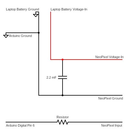
- 1 * 9volt battery
- 1 * laptop charger
Sensing:
- 1 * Adafruit MiCS5524 sensor (this was the air pollution sensor we used because it’s cheap. The drawback is that it senses multiple gases and does not distinguish between them)
Other:
- 2 * white t-shirt (we suggest buying t-shirts that are too big because 1) there needs to be room for the hardware and 2) you’ll need to cut off a bit of extra fabric in order to make a pocket to hide the hardware)
Tools:
- Jumpers
- Protoboard
- Capacitor
- Resistor
- Wire cutter
- Soldering machine
- Sewing material and/or fabric glue
Step 2: Assembling the NeoPixel Grid
In order to assemble the NeoPixel grid, the original NeoPixel strips need to be cut and re-soldered depending on the desired grid dimensions. For this design, we were building a 47×16 grid of NeoPixels:
- Cut the 1-meter (144 NeoPixel) strips in 47 NeoPixel increments, being careful to allow for some room to solder at the edges of the strips (there are small metal leads that are visible on the bottoms of the NeoPixels). Make sure to cut such that the entire soldering pad is exposed (because they are already so small to begin with). The reason the strips are 47 pixels instead of (144/3 = 48) pixels long is that you’ll lose at least one from cutting them because the NeoPixel’s are so close together.
- Carefully lay the columns out next to one another (optionally use electrical tape to hold them in place), and ensure that the dimensions are as desired (47×16). Lay out the columns in an S-pattern.
- The NeoPixels have leads for voltage-in, input, and ground that should be connected to their counterparts in the next strip. Using multi-strand wire, connect the columns’ leads together in an S-pattern, being careful to connect the correct leads.
- Leave the leads at the ends of the grid (there should be 2 ends – one where you began, and one where you ended the S-pattern), and optionally add wire extensions for convenience. You may also optionally tape off or otherwise secure the leads at the end. Also, hot glue over the connections to secure them.
- Ensure that your newly assembled grid is secure by adding a few more layers of electrical tape or other adhesive to the back.
Now you should have a working grid that you can test. Under the NeoPixel Matrix library, you can use the matrixtest sample code to see if the grid is working as expected. If it does, it should look like the photo above (ignore the Arduino Uno in the front, it was for testing something else)
Step 3: Adding the Sensor
A key aspect of this project is the sensor, an Adafruit MiCS5524, which can detect varying gases in the air and signal their intensity through analog input.
- First, ensure that the three leads to the sensor – voltage-in, output, and ground – have been wired correctly (optionally use appropriately colored wire to aid in this).
- Connect the voltage-in to the 5V output on the Arduino board, and connect the ground to the ground on the board.
- Then, connect the output to the A0 (or analog pin of your choice) on the Arduino board. This is all that is necessary in order to connect the sensor to the Arduino.
- Optionally, use the Serial monitor to verify that readings are being reported by the sensor (the readings should hover around one number and change when the sensor is placed near a source of carbon monoxide or other fumes).
Online, there are instructions for calibrating this sensor in particular so that it is sensitive to a change in the environment. What we did was leave the sensor for a few hours to determine what a “regular” reading range was for the room it was in. Then, to test “triggering” of the display, we used a cotton ball soaked in rubbing alcohol so that the sensor reading would spike above a set threshold to begin one loop of the graphic.
Step 4: Debugging the Code
Attached is the code. Notice that there are many headers included at the top. To download the required headers, in the Arduino IDE, click sketch, include library, and then manage libraries. Before you can upload the attached file, you’ll need to download the following libraries:
- Adafruit NeoPixel
- Adafruit NeoMatrix
- Adafruit GFX library
Once you’ve downloaded these libraries, in the Arduino IDE, under file, examples, you’ll find example code that can be modified to test as you go. For example, strandtest and matrixtest were very useful for testing the NeoPixel grid. Online, it’s also easy to find sample tests for the air pollution sensor.
Read more: EqualAir: Wearable NeoPixel Display Triggered by Air Pollution Sensor