Summary of DIY Arduino Mini Laser Engraver
Summary: This instructable shows how to build a mini laser engraver from two salvaged DVD writer sliding mechanisms, a custom PCB, Arduino Nano, A4988 drivers, and a 250 mW 650 nm laser. The author details disassembly, acrylic frame fabrication, motor wiring, mounting, PCB fabrication, soldering, and configuring microstepping and wiring for reliable laser control and power.
Parts used in the Mini Laser Engraver:
- Arduino Nano
- 250mW 650nm Laser Module
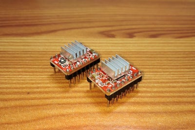
- A4988 Motor Driver
- IRFZ44N MOSFET
- LM7805 Voltage Regulator
- Laser Heatsink
- IC Heatsink
- 1000uF Capacitor
- 10k Resistor
- 47R Resistor
- Male and Female Header Pins
- Screw Terminal
- JST 2.0 Connector
- 2.5mm Jumper Cap
- Shrink Tube
- Two DVD Writer Sliding Mechanisms
- Custom PCB Board (JLCPCB)
- 5mm Acrylic Sheet
- Stepper motors (from DVD writers)
- M3x12 Screws and bolts
- 6mm standoff spacers
- 5mm hex nylon PCB spacers
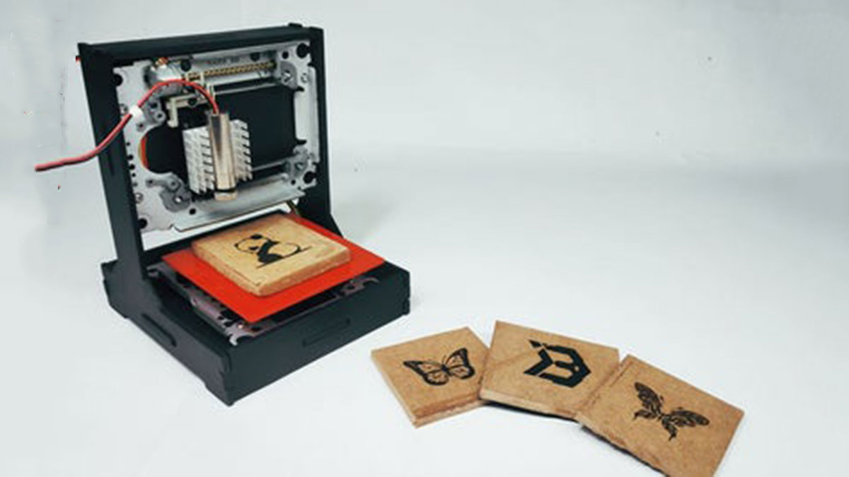
Hello Guys Whatsup, In this instructable, I am making an Awesome mini laser engraver from old DVD writers. It’s an amazing machine. You can use this laser engraver machine to make any kind of design, logo, art on the surface like WOOD, MDF, PLYWOOD, VNYL Paper. It’s little difficult to make a high-resolution laser engraver from DVD writer. But I tried my best to make a pretty close one. In this instructable, I am going to show you the entire procedure of how I made this DIY Laser Engraver. So let’s get started 🙂
IF YOU LIKE THIS PROJECT THEN DON’T FORGET TO VOTE FOR ME, I AM PARTICIPATING IN REMIX CONTEST
PROJECT INSPIRATION
I got this Laser engraver’s idea from Maggie Shah. Here’s the version of his laser engraver https://www.instructables.com/id/Mini-CNC-Laser-Wood-Engraver-and-Paper-Cutter/ . I remixed his project with my own touch.
Here’s the full video tutorial Video
Step 1: Parts List
We need these following parts to make this project.
- Arduino Nano
- 250mW 650nm Laser Module
- A4988 Motor Driver
- IRFZ44N Mosfet
- LM7805 Voltage Regulator.
- Laser Heatsink
- IC Heatsink
- 1000uF Capacitor
- 10k & 47R Resistor
- Male And Female Header Pin
- Screw Terminal
- JST 2.0 Connector
- 2.5mm Jumper Cap
- Shrink Tube
- DVD Writer
- Custom PCB Board
- 5mm Acrylic Sheet
Tools List:
- Soldering Iron
- Drill Machine
- Metal File
- Sandpaper
- Wire Cutter
- Superglue
Step 2: Remove the Stepper Sliding Mechanism
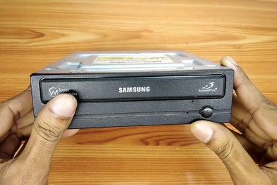
We need two DVD writers mechanism for this project. One for X-Axis and another one for Y-Axis. You can find this DVD writer from broken CPU or local hardware shop. I also got from the local hardware shop at very cheap prices. Now its time to disassemble the DVD writers.
- Use Philips head screwdriver to remove all the screws.
- Unplugged all the connectors and cables.
- Open the disk holder and unscrew the sliding mechanism.
- Detached the Sliding mechanism.
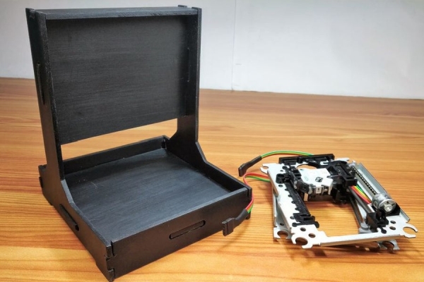
Step 3: Assemble the Frames
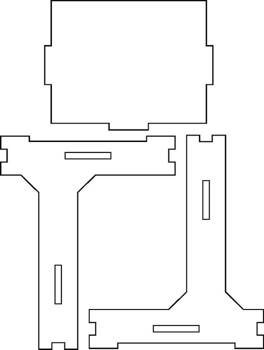
Here I’ve used 5mm acrylic to make the frame. It is a very good choice for making the enclosure for every DIY Project. Personally, I frequently use this sheet to make the enclosure for my DIY Projects. It is easy to cut, bend and sand. I made the printable templates to make the laser engraver more stable.
- First, print the templates then attach the templates to the acrylic sheet using the glue stick.
- Carefully cut the acrylic sheet according to the template’s design using a jigsaw or mini handsaw.
- Remove the plastic cover from acrylic and sand all the pieces to get the smooth matte finish.
- Use super glue to attach all the pieces together.
Step 4: Wiring of Stepper Motor
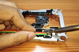
In this step, I’ll solder wires to the stepper motors. Follow the steps below to properly solder wires.
- First, determine the 2 coils A and B using multimeter’s continuity mode.
- Cut the flexible PCB of stepper motors.
- Solder wires to stepper motors
- Connect 1*4 Female header pin at the end of wires and secure them using shrink tube.
Step 5: Making Holes for Sliding Mechanism
In this, I’ll make the holes to mount the sliding mechanism.
- First properly position the sliding mechanism on the engraver frame.
- Mark the holes using a screwdriver.
- Use 3mm drill bit to make the holes.
Step 6: Attach Spacer
Here, I am attaching 6mm standoff spacer with the sliding mechanism before mounting it on the engraver frame. It will help to reduce the vibration to get high precision engraving.
Step 7: Mount the Sliding Mechanism

Now I’ll mount the sliding mechanism.
- Attach 5mm hex nylon PCB spacer before mounting the slider.
- Use 4xM3x12 screw to attach the sliding mechanism.
- Attach bolt with the screw to tighten more securely.
Step 8: Mount the Engraving Platform
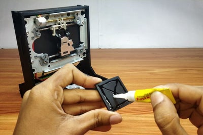
Now we need to attach the engraving platform. I started off by attaching 3cm square acrylic using superglue. after that i attached the main engraving platform. which dimention is 9x9cm. It would be better you use a metel grill for the engraving platform.
Step 9: The PCB Making
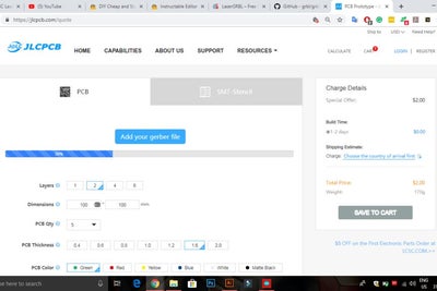
In this project, i am using custom designed circuit board to give more profesional touch. So i chose JLCPCB to design and order the custom designed PCB for this project.
Circuit Schematic link
Gerber File link
About JLCPCB
JLCPCB (Shenzhen JIALICHUANG Electronic Technology Development Co., Ltd.), is the largest PCB prototype enterprise in China and a high-tech manufacturer specializing in quick PCB prototype and small-batch PCB production. With over 10 years of experience in PCB manufacturing, JLCPCB has more than 200,000 customers at home and abroad, with over 8,000 online orders of PCB prototyping and small quantity PCB production per day. The annual production capacity is 200,000 sq.m. for various of 1-layer, 2-layer or multi-layer PCBs. JLC is a professional PCB manufacturer featured of large scale, well equipment, strict management and superior quality.
Related download files
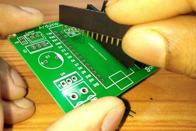
You can get the Circuit (PDF) file from here. As you can see in the pictures above the PCB is very well manufactured and I’ve got the same PCB design that we’ve made for our main board and all the labels and logos are there to guide me during the soldering steps. You can also download the Gerber file for this circuit from here in the case you want to place an order for the same circuit design. If you want to design your own version of PCB you can design it on JLCPCB family site which called EasEDA. It’s so simple and easy to design pcb for DIY projects.
Step 10: Soldering All the Components
Now its soldering time. use clean fine soldering tip. first I started off by soldering all the small components like header pins then solder other components according to the circuit diagram.
You can make this circuit on a perf board. It’s very simple and easy. just follow the circuit schematic which I mentioned above. But first, make it on a beard board to check everything works perfectly then you can go for the pref board
Step 11: Mount the Arduino and Motor Drivers
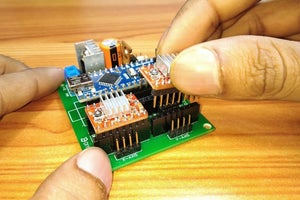
Now mount the Arduino and A4988 motor drivers.
In GRBL the digital and analog Pins of Arduino are reserved. The ‘Step’ pin for the X and Y axes is attached to digital pins 2,and 3 respectively. The ‘Dir’ pin for the X and Y axes is attached to digital pins 5 and 6 respectively. D11 is for laser Enable. The Arduino gets power through the USB Cable. The A4988 Drivers through external power source. All ground share common connections. VDD of A4988 are connected to 5V of Arduino. The laser I’ve used runs on 5V and has built in constant current circuit. For the constant 5V source from the external power supply LM7805 voltage regulator is used. Heatsink is compulsory. The IRFZ44N N-CHANNEL MOSFET works as an elelctronic switch when receives digital high signal from pin D11 of Arduino. NOTE: 5V from Arduino nano can’t be used beause the laser draws more than 250mA and the Arduino Nano is not capable of delivering that much of current.
Configuring Micro Stepping for Each Axis.
MS0 MS1 MS2 Microstep Resolution.
Low Low Low Full step.
High Low Low Half step.
Low High Low Quarter step.
High High Low Eighth step.
High High High Sixteenth step.
The 3 pins (MS1, MS2 and MS3) are for selecting one of the five step resolutions according to the above truth table. These pins have internal pull-down resistors so if we leave them disconnected, the board will operate in full step mode. I’ve used the 16th step configuration for smooth and noise free. Most (but certainly not all) stepper motors do 200 full steps per revolution. By appropriately managing the current in the coils it is possible to make the motor move in smaller steps. The Pololu A4988 can make the motor move in 1/16th steps – or 3,200 steps per revolution.The main advantage of microstepping is to reduce the roughness of the motion. The only fully accurate positions are the full-step positions. The motor will not be able to hold a stationary position at one of the intermediate positions with the same position accuracy or with the same holding torque as at the full step positions.Generally speaking when high speeds are required full steps should be used.
Source: DIY Arduino Mini Laser Engraver
- What materials are used for the frame?
5mm acrylic sheet is used for the frame and enclosure. - Can DVD writers be used for both axes?
Yes, two DVD writer sliding mechanisms are used: one for the X-axis and one for the Y-axis. - How is the laser powered safely?
An external 5V source regulated by an LM7805 is used because the Arduino 5V cannot supply the laser current. - Which MOSFET controls the laser?
The IRFZ44N N-channel MOSFET is used as the electronic switch for the laser, driven by Arduino pin D11. - How are the stepper motors wired?
Coils are identified with a multimeter, wires soldered, and a 1x4 female header added; connections follow the A4988 driver pins. - What microstepping configuration is recommended?
The author used 1/16 microstepping (MS0 MS1 MS2 high high high) for smooth and noise-free motion. - Where was the custom PCB manufactured?
The custom PCB was ordered from JLCPCB and assembled according to the provided schematic and gerber files. - How should components be soldered first?
Solder small components and header pins first, then larger components, and test on a breadboard or perf board before final assembly. - What tools are needed for the build?
Required tools include a soldering iron, drill machine, metal file, sandpaper, wire cutter, jigsaw or mini handsaw, and superglue. - What materials are recommended for the engraving platform?
The author used a glued acrylic square and a 9x9 cm main platform but suggests a metal grill is better for the engraving platform.