
Summary of DIY: Arduino Based Ohmmeter
This Arduino-based project functions as a multi-functional meter capable of measuring unknown resistance, identifying diode types (Silicon or Germanium), and testing circuit continuity. Utilizing an Arduino Pro Mini's ADC and a voltage divider concept, the system processes input voltages to calculate values. Results are shown on a 16x2 LCD, while a blinking LED indicates continuity. The architecture comprises a sensor unit for inputs, a processor unit for calculations, and a display unit for output.
Parts used in the Arduino Based Ohmmeter:
- Arduino pro mini board
- Breadboard
- 16x2 LCD
- Voltage Divider circuit
- LED
- Probes
This is a project based on Arduino board which can measure the unknown resistance values and perform diode test and continuity testing. When we connect the unknown resistor on the breadboard circuit, the 16×2 LCD displays the resistor value and when we connect a diode the LCD displays the type of diode if it is a good one. When we take the probes out from the breadboard and connect it across a continuous path, the meter indicates the continuity by blinking an LED.
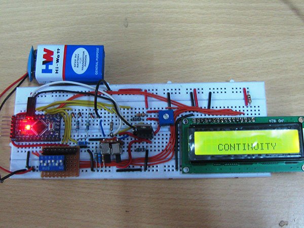
The project uses an Arduino pro mini board whose ADC feature is used along with the concept of Voltage Divider circuit to develop this Ohmmeter.
Architecture of the project
The entire project can be divided into three basic blocks;
1) Resistance/Diode/Continuity Sensor Unit
2) Processor Unit
3) Display Unit
The Sensor Unit takes three inputs, Unknown resistor, Diode and a Continuous path to be detected. When the unknown resistor is connected as input, the output voltage varies between 0 and 5V proportional to the value of resistance. When the unknown diode is connected as input, the output voltage will be 4.3V for Silicon diode and 4.7V for Germanium diode. When a continuous path is connected as input, the output voltage will be 5V.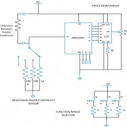
The Processor Unit takes input voltage in the range of 0 to 5V. This unit calculates the resistance value, detects the diode type and continuous path from the input voltage value. The unit then sends a 4bit data to the Display Unit which includes the resistance value or diode type. The Processor Unit also glows an LED if it detect a continuous path.
The Display Unit takes the 4bit data from the Processor Unit and produces a 16*2 display for the resistance value, diode type.
For more detail: DIY: Arduino Based Ohmmeter
- What components are used in this project?
The project uses an Arduino pro mini board, breadboard, 16x2 LCD, Voltage Divider circuit, LED, and probes. - How does the project measure unknown resistance?
It uses the Arduino pro mini ADC feature along with the concept of a Voltage Divider circuit. - Can this device identify different diode types?
Yes, it displays the type of diode if it is good, distinguishing between Silicon and Germanium diodes. - Does the meter indicate continuity with sound or light?
The meter indicates continuity by blinking an LED when a continuous path is connected. - What voltage range does the Processor Unit accept?
The Processor Unit takes input voltage in the range of 0 to 5V. - How does the Sensor Unit distinguish between inputs?
It detects outputs based on voltage variations: proportional to resistance, 4.3V for Silicon, 4.7V for Germanium, and 5V for a continuous path. - What happens when the probes are taken out from the breadboard?
The meter waits for connection across a continuous path to blink the LED indicating continuity.
