Summary of Arduino Powered Four Letter Word Generator
This article details building an Arduino-based "Four Letter Word Generator" using a Siemens DL2146T 16-segment display to emulate vintage Nixie tube aesthetics without high voltage. The project utilizes an ATMEGA168 microcontroller and generates random words on-the-fly rather than using a pre-stored list. It is designed for beginners with soldering skills, featuring a custom acrylic filter for enhanced glow effects and requiring specific components like a protoboard, ribbon cable, and power supply.
Parts used in the Arduino Powered Four Letter Word Generator:
- Siemens DL2416T display
- Atmel ATMEGA168 microcontroller
- 28-pin narrow DIP socket or 2x 14 pin DIP sockets
- 40-pin DIP socket
- PB400 protoboard from Wright Hobbies
- 1 ft 16-conductor rainbow ribbon cable
- 2x 0.1 uf mono caps
- 2x 22uf 16v radial electrolytic caps
- 16mhz ceramic resonator
- 10k Ohm 1/4 watt resistor
- 2.1mm power jack 1 mm lead size
- 5v switchmode wall power supply
- 8 x 10 sheet of 1/8 clear red acrylic
- Hook-up wire
- Standoffs and mounting hardware
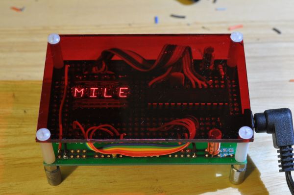
Build an Arduino-powered version of the “Four Letter Word Generator” (FLW). This version generates “words” on the fly – it does not use a list. The “original” version from the 1970’s used B7971 nixie alphanumeric tubes. These tubes are getting hard to find and they’re certainly expensive. They also require interfacing with high voltage and an understanding of multiplexing.
This version uses a slightly more modern and easier to use display while maintaining the overall glowy, multi-segment look of the original. The Siemens DL2146T is a 4-character, 16-segment (plus dot) intelligent display. It has built-in drive and an ASCII font table. You basically send it seven bits of ASCII along with a couple more bits that select the position and control reset, blanking and chip select. It uses “a lot” of pins but we’re not doing anything else so the available outputs on a ATMEGA168 are plenty.
An Arduino beginner with good soldering skills should be able to complete this.
Step 1: Parts List
1x Siemens DL2416T display
This is an obsolete part, but it is generally available. You should pay less than $20 USD for it.
Here are some websites that had it in stock at the time of publishing this instructable:
http://www.alltronics.com/cgi-bin/category.cgi?item=DL2416T
http://www.intertexelectronics.com/DL2416T-160-Red-4-Character-16Seg-Alphanumeric-Intelligent-Display-P8698.aspx
http://www.electronicsurplus.com/item/39202/
1x Atmel ATMEGA168
Buy this wherever you get the best price. You can get it with the bootloader already installed if you want.
An ATMEGA328 will work but is overkill. An ATMEGA8 might also work but I have not personally tried it.
1x 28-pin narrow DIP socket or 2x 14 pin DIP sockets
1x 40-pin DIP socket
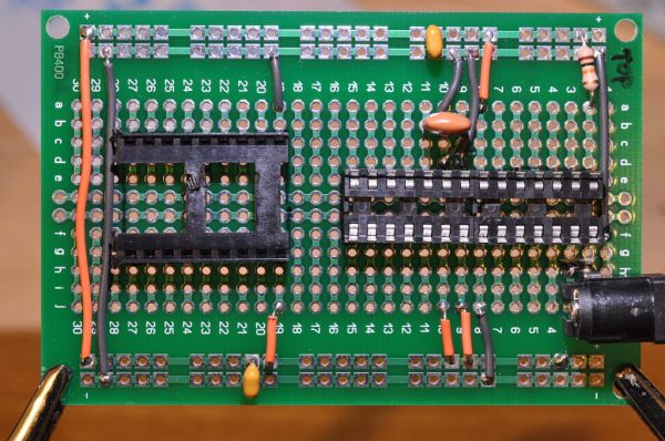
1x PB400 protoboard from Wright Hobbies http://www.wrighthobbies.net/
Feel free to use whatever you want, but this is a great quality protoboard and it is cheap, esp. if you buy a five-pack.
This board is double-sided, real fiberglass, tinned and all the holes are through-hole-plated.
You’ll appreciate how nicely it solders and how well you can unsolder without ripping up pads.
1x 1 ft 16-conductor rainbow ribbon cable
Try jameco.com for this one; it’s not mandatory but the colors help keep you from messing up the bus wiring.
2x 0.1 uf mono caps
2x 22uf 16v radial electrolytic caps (anything 10uf – 47uf is fine)
1x 16mhz ceramic resonator
1x 10k Ohm 1/4 watt resistor
1x 2.1mm power jack 1 mm lead size
Try moderndevice.com – use the one they sell for the RBBB
1x 5v switchmode wall power supply
Try bgmicro.com – they have a 5v 2a for $3.99
I used to make my own linear regulator setups on-board for wall-powered stuff, but a regulated switchmode supply
is so much more efficien and they are cheap, so I no longer bother.
Make sure to observe the polarity of your adaptor. Most use center positive. Adapt your wiring for the jack if necessary.
1x 8″ x 10″ sheet of 1/8 clear red acrylic
Ebay is the best option here.
General parts:
– hook-up wire – solid core is easiest but consider looking into teflon-insulated wire – costs more, harder to strip but it does not shrink or melt when soldering.
– get a “grab bag” of standoffs and mounting hardware – try alltronics.com, bgmicro.com or goldmine-elec.com
Step 2: Tools List
The following are necessary for doing the project:
– soldering iron
– 60/40 solder
– screwdriver
– wire cutters
– wire pliers
– scoring knife
– wood clamps or a vise
– a table with a sharp edge and a sturdy straight edge, or two pieces of square cut hardwood
– arduino board or clone and/or an in-circuit ATMEGA programmer; I use a usbtiny kit from www.adafruit.com
Ooptional, but nice to have:
– “helping hands” or PanaVise board holder
– temperature-controlled soldering iron (trust me, it’s worth the investment)
– multimeter
– gaffer’s tape (found in high-end camera stores and theatrical supply houses)
Step 3: The Prototype
Here’s the original as developed on a breadboard with jumpers. The Arduino is an Adafruit Boardiuno kit. It’s meant to plug right into a breadboard. It works very well for that purpose. The flexible jumper wires are also a worthwhile investment.
Step 4: Fabricating the Display Filter
The following few steps are optional but they improve the look of the display. If you want the display filter, do it now before you solder anything to the board. Otherwise you won’t be able to use the board as a template, unless you bought more than one.
1x Atmel ATMEGA168
1x 28-pin narrow DIP socket or 2x 14 pin DIP sockets
1x 40-pin DIP socket
1x PB400 protoboard
1x 1 ft 16-conductor rainbow ribbon cable
For more detail: Arduino Powered Four Letter Word Generator
- What type of display does this project use?
The project uses a Siemens DL2146T which is a 4-character, 16-segment intelligent display with built-in drive and an ASCII font table. - Can I use an ATMEGA328 instead of the ATMEGA168?
An ATMEGA328 will work but is considered overkill for this specific project. - Does the generator use a pre-stored list of words?
No, this version generates words on the fly and does not use a list. - How do you fabricate the display filter?
You should cut an 8 x 10 sheet of 1/8 clear red acrylic, ideally sourced from eBay, to improve the look of the display. - Is a 5v linear regulator required for power?
No, the article recommends using a regulated switchmode supply because it is more efficient and cheap. - What kind of protoboard is recommended?
A PB400 protoboard from Wright Hobbies is recommended because it is double-sided fiberglass that solders well. - Can an ATMEGA8 be used for this project?
An ATMEGA8 might also work, though the author has not personally tried it. - What tools are necessary for soldering the project?
Necessary tools include a soldering iron, 60/40 solder, screwdriver, wire cutters, and wire pliers.