Summary of DIY 3D Laser Scanner Using Arduino
Alessandro Grossi describes a DIY 3D laser scanner that uses a line laser, a DSLR, and an Arduino-driven stepper to rotate a laser-camera arm and trigger synchronized photos. By projecting a laser plane onto an object and capturing images at known angles, the system reconstructs depth via triangulation. The build emphasizes careful mechanical alignment, a simple motorized holder, and Arduino code that controls the stepper and emulates an IR camera remote for synchronized shooting.
Parts used in the DIY 3D Laser Scanner:
- Line laser (red, nominal 100 mW used)
- DSLR camera
- Arm or holder for laser and DSLR (chipboard or similar)
- Stepper motor
- Stepper motor driver (with pul, dir, enable inputs)
- Arduino (to control stepper and mimic IR remote)
- Infrared LED (connected to Arduino pin 13)
- Panoramic head or mounting collar (optional for nodal rotation)
- Tools and fasteners (hot glue, screws, drill press or lathe for shaft hole)
Maker Alessandro Grossi sent us this great DIY build for a 3D scanner built using a laser, a DSLR, and an Arduino controller. Allesandro is a Mechanical Engineer, holding a Ph.D. in product design. His day job involves helping designers and manufacturing firms develop and optimize products by means of FEM analisys and Computational fluid dynamics. This is just what he does for fun. You can read the project and more on his own site, metaingegneria.com.
Here’s Alessadro’s project description:
A line laser is a laser equipped with a cylindrical lens, in this case I used a red laser, but other colors can be used, like green or blue. The lens opens the beam shaping it into a plane. The one I used in this experiment is characterized by a nominal power of 100mW (not up to standard in Italy, I think the max allowed power is 5mW) but the beam does not remain focused in a single ray, it is extended in a plane, so the intensity quickly drops below dangerous levels.
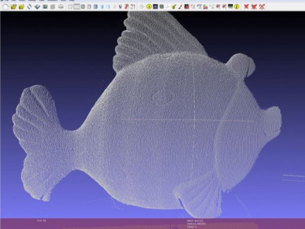
The principle behind this scanner is the typical of a line scanner. A laser beam intercepts the object to be measured and a camera, positioned at a known angle and distance shoots a series of images. With some trigonometry considerations and optic laws it is relatively easy to reconstruct the Zeta dimension, the measurement of the distance between the object and the camera.
Commercial systems based on this principle, named line scanner or profilometers, are used in industries and are typically characterized by a high frame rate (even 200 or more frames per second) and a strength suitable for industrial uses. An industrial profilometer price ranges from a few thousand Euros to several tens of thousands of Euros. The cost of the components for the system I propose here does not exceed 100/150 €, if you already have an SLR.
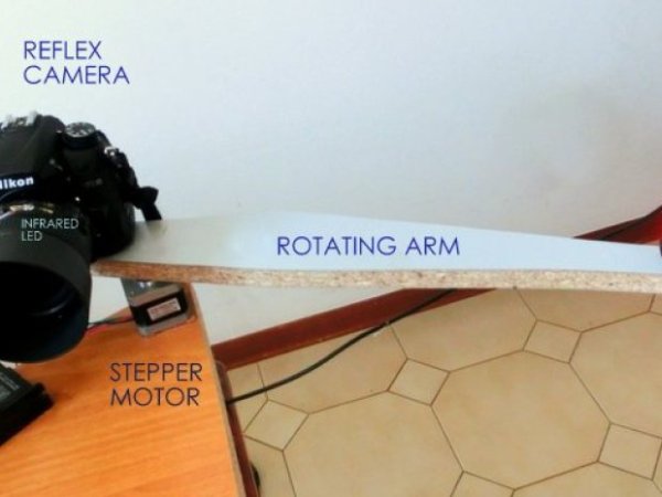
Step #1: Holder arm for laser and DSLR
- Using hot glue, welding or the method you prefer, connect the camera and the laser ball head at an arm whose length is about 40/50 cm. When the three parts are connected (laser head, arm and camera) locate the assembly center of gravity (approximately). In that position drill an hole for the stepper motor shaft. It would be geometrically easier to use a panoramic head, which grants the ability to turn the system around the lens nodal point, but that would require a more rigid system, certainly not achievable with a simple piece of chipboard, and a shaft simply forced in an hole.
- Pay attention to obtain the parallelism between the hole axis, the vertical axis of the image captured by the camera and the laser plane! I suggest you make the hole that houses the motor shaft using a drill press, or, if you have access to a lathe, you could realize a collar to ensures the orthogonality between the motor axis and the arm. Moreover, the laser plane will be, in turn, perpendicular to the plane of the arm and the camera must be perfectly horizontal and leveled. Assembling everything you should get something that looks like the system I show in the picture. I’m waiting for pictures of your own solutions! mail me at [email protected]
Step #2: Rotation and camera synchronization
- The second step is to put everything in rotation and to synchronize the camera. The fastest and easiest way I’ve found to achieve this synchronization is to use an Arduino to mimic the infrared remote control and to control the stepper motor. -the infrared led is connected to pin 13 (and ground) -the 3 inputs of the driver (pul, dir, enable) are connected to pins 10,11 and 12
- the Arduino code I used is:/*
Stepper Motor Control +camera control
*/
int pinIRLED = 13; // infrared led
int pul = 10;
int dir = 11;
int enbl = 12;
int passi = 4; // numero passi su 12800
int intervallo = 3; // intervallo tra i passi
void setup() {
pinMode(pinIRLED, OUTPUT);
pinMode(pul, OUTPUT);
pinMode(dir, OUTPUT);
pinMode(enbl, OUTPUT);
digitalWrite(enbl, HIGH);
}
void pulseON(int pulseTime) {
unsigned long endPulse = micros() + pulseTime; // create the microseconds to pulse for
while( micros() < endPulse) {
digitalWrite(pinIRLED, HIGH); // turn IR on
delayMicroseconds(13); // half the clock cycle for 38Khz (26.32×10⁻⁶s) – e.g. the ‘on’ part of our wave
digitalWrite(pinIRLED, LOW); // turn IR off
delayMicroseconds(13); // delay for the other half of the cycle to generate wave/ oscillation
}
}
void pulseOFF(unsigned long startDelay) {
unsigned long endDelay = micros() + startDelay; // create the microseconds to delay for
while(micros() < endDelay);
}
void takePicture() {
for (int i=0; i < 2; i++) {
pulseON(2000); // pulse for 2000 uS (Microseconds)
pulseOFF(27850); // turn pulse off for 27850 us
pulseON(390); // and so on
pulseOFF(1580);
pulseON(410);
pulseOFF(3580);
pulseON(400);
pulseOFF(63200);
} // loop the signal twice.
}
void loop() {
// ciclo per dare gli step al driver dello stepper
for (int ii=0; ii<passi; ii++){
digitalWrite(pul, HIGH);
delay (intervallo);
digitalWrite(pul, LOW);
delay (intervallo);
}
delay(1600); // questo intervallo è necessario per garantire che il braccio abbia terminato le oscillazioni prima di riprendere l’immagine
takePicture(); // take the picture
delay(200);
} - Now the assembly is ready and it should work more or less like this: Watch video here.
For more detail: DIY 3D Laser Scanner Using Arduino
- What principle does the scanner use?
The scanner uses a line scanner principle: a laser plane intersects the object and a camera captures images at known angles to reconstruct depth via triangulation. - How is the camera synchronized with rotation?
An Arduino mimics the camera infrared remote to trigger shots while also driving the stepper motor. - Which Arduino pins are used for the IR LED and motor driver?
The IR LED is on pin 13; the motor driver pul, dir, and enable are connected to pins 10, 11, and 12 respectively. - What mechanical alignment is important for the build?
The motor shaft axis must be parallel to the camera vertical image axis and the laser plane; the camera must be horizontal and leveled. - What laser was used in the project?
A red line laser with nominal power of 100 mW was used in the experiment. - How much do the components cost according to the article?
The cost of components does not exceed about 100 to 150 euros if you already have an SLR. - Why might a panoramic head be useful?
A panoramic head allows rotation around the lens nodal point, simplifying geometry, though it requires a more rigid mount. - What does the Arduino code do besides moving the stepper?
It pulses the IR LED with timings that emulate an infrared remote to remotely trigger the DSLR for each position.