
Summary of Dark Sensor With LDR, Transistor and a LED
This tutorial guides beginners on building a simple dark sensor circuit using an LDR, a transistor, and an LED. The project operates by detecting light levels; the LED remains off in bright conditions but illuminates when the LDR is obstructed from light. The guide details component requirements and step-by-step assembly instructions on a breadboard to create a functional electronic switch.
Parts used in the Dark Sensor Project:
- Breadboard
- 12v Power source
- BC547 Transistor
- 1KOhm Resistor
- 680KOhm Resistor
- Blue LED
- LDR (Light Dependent Resistor)
- Conductor cables
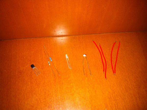
You wan’t do a dark sensor with a LDR, one transistor and one LED and you don’t know how to do it? In this small tutorial I will explain to you how you can do that even if you know only the basics of electronic.
Parts you need:
1 Breadboard;
1 Power source of 12v;
1 Transistor (in this case we use the BC547);
1 Resistor of 1KOhm;
1 Resistor of 680KOhm;
1 LED (in this case blue);
1 LDR:
Some condutor cables to connect the parts.
Step 1: Connecting Parts in the Breadboard
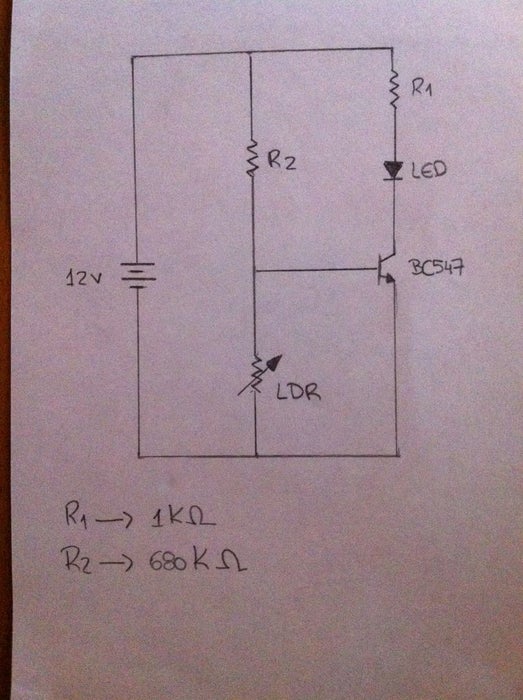
In the above image we can see the circuit we will construct. It’s a simple electronic circuit and if you know how to do something on a breadboard, you should be able to do that dark sensor.
Step 2: Connect Everything
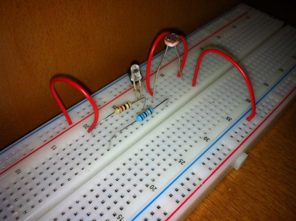
Just do the circuit like this and all should be working fine.
Remember, the LDR resistance depends on the light you have on the room or where you are constructing that. If you have light, the LDR resistance is low so, the LED should be turned off. When you obstruct the light that focus on the LDR, the LED should light up.
If for any reason your LED is always lighted up, try to chance the transistor. Switch the Emissor and the Collector. If the problem persist, increase the resistor you have in the base.
Step 3: All Should Be Working
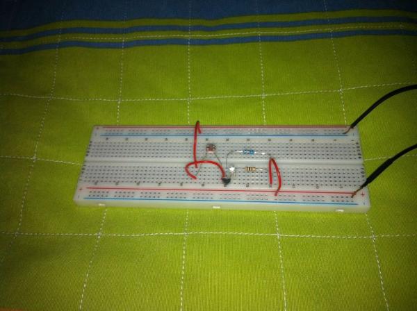
Connect the power source you have to the breadboard. The positive pole in the red line and the negative in the blue line.
Try your circuit and see what happens.
Here’s the video of my circuit working:
If you have any questions feel free to ask in the coments. If you think I should improve something, let me know. It’s my first guide so it’s normal I made some mistakes.
Source: Dark Sensor With LDR, Transistor and a LED
-
How does the LDR resistance affect the LED?
In bright light, the LDR resistance is low causing the LED to turn off, while obstructing the light makes the LED light up. -
What should I do if my LED is always lit?
Try changing the transistor or switching the Emissor and Collector connections. -
Can I use this circuit if I only know basic electronics?
Yes, the tutorial explains how to build it even if you know only the basics of electronics. -
How do I connect the power source to the breadboard?
Connect the positive pole to the red line and the negative pole to the blue line. -
What happens if the problem persists after switching the transistor?
You should increase the resistor you have in the base. -
Which specific transistor model is used in this example?
The BC547 transistor is used in this case. -
Does the ambient light level change the circuit's behavior?
Yes, the LDR resistance depends on the light present in the room where the construction takes place.
